We have been experimenting with VFDs to run conventional AC Pumps using DC power of solar panels as in previous post (HP Size Solar Pumps) This is because there are a couple of good quality Solar MPPT VFDs easily available at fair prices.
However the VFD requires relatively high DC input voltage, 290 to 360VDC to run a single phase AC pump, and 440+VDC to run a three phase pump.
At sub-HP power levels the solar panels in commercially available sizes (250 to 330 Watt and 36 to 44 VDC each) are most often not going to add up to the input voltage requirements even for a VFD that will run a single phase AC pump.
To deal with this issue, there is a thought process that some kind of DC to DC boost converter can be used from low voltage DC source to raise the DC voltage in the acceptable range for to the VFD.
As a quick check a small experiment was carried out involving following components.
DC source from 8 x 60 W 36VDC array of panels but on a fully cloudy day. The open circuit voltage at the panel output was around 24 to 34 VDC.
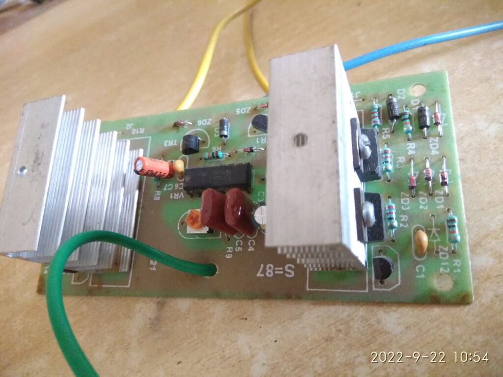
A low cost inverter board that runs on SG3524 chip and MOSFETs, it produces approximately 50 Hz square wave AC output.
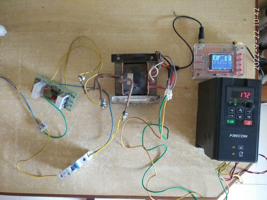
3. Salvaged transformer from a household inverter, 12-0-12V to 230V centre tapped, this is rated for around 700VA.
4. Frecon make solar VFD for single phase AC output.
The overall assembled setup is shown in the next picture.
To measure the output voltage and to view the wave pattern, a hobbyst’s oscilloscope (DSO138) was used. At the high voltage side output of the transformer a voltage divider comprising of 22kohm, 1.6kohm and 22kohm was connected. The measuring probes of the oscilloscope were connected across the central 1.6kohm resistor, thus the voltage measured on the oscilloscope is scaled down by a ratio of 1.6 : 44 (i.e. 1 : 27.5). Or in other words, the measured voltage on oscilloscope need to be multipled by 27.5 to get the actual voltage level at the transformer output.
Observations
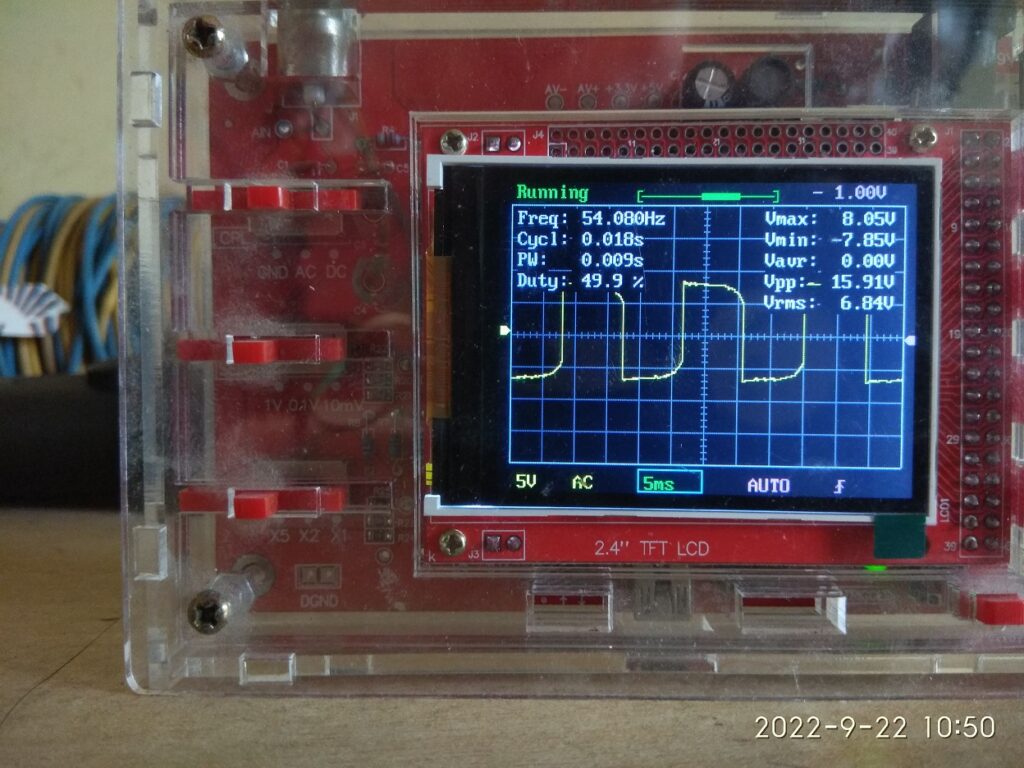
When the DC power was applied to the inverter and VFD was connected to the transformer output, but not yet switched on, the output from transformer showed as in below picture. Oscilloscope showing 8V means the AC output was +220/-220 V peak to peak and 6.84 x 27.5 = 188 VAC RMS. The DC voltage at inverter input was seen to be in range of 12V.
In this case, the LED display of VFD showed a DC input voltage as 172 VDC. This is not really adequate for a single phase solar VFD, while it requires 290 to 360VDC input for normal operation.
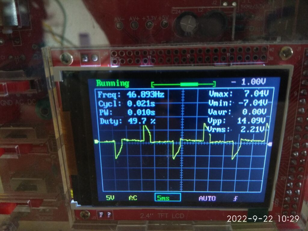
When VFD was switched on, the output voltage from transformer was seen to be reduced. Oscilloscope showing 7.04V means the AC output was +193/-193 V peak to peak, and 2.21 x 27.5 = 61 VAC rms. The DC voltage at inverter input was at 6V. More importantly the waveform is highly distorted and is most likely due to not enough driving power for the transfomer of the inverter, suggestive of shortfall in power available from solar panels.
It would be fair to conclude that this conept as such is ok but the voltage levels and power efficiency need to be experimented further and evaluated.
Adequate power and volage from Solar panels need to be made available on a bright sunny day.
May be, high frequency switching with suitable ferrite or equivalent transformer need to be used.
TBD.Centrifugal pumps running on normal AC power supply are very common, fairly efficient and most importantly they are locally available from wide range of manufacturers. Their use and operation is more or less hasslefree, they are easily serviceable at nearby workshops and pricewise also they are affordable. These points are specifically important in comparison to a classical solar pump system that is available in market these days, and which potentially uses a BLDC 3 phase DC motor/pump with permanent magnets and all stainless steel body.
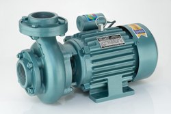
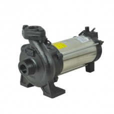
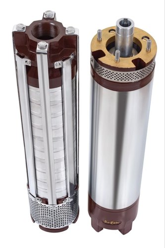
TBD.These standard AC pumps are available in 0.5 HP to 10s of HP of power rating, able to run on single phase (220V) or three phase (415V) AC power supply and available in formats like monoblock pumpset, openwell submersible and borewell submersible pumps.
TBD.Monoblock PumpTBD.Openwell Submersible PumpTBD.Borewell Submersible Pump, motor and pump shown separated from each other.
TBD.This article discusses the use of such standard AC pumps using Solar Panels as the source of electricity.
TBD.Since solar panels generate TBD.DC voltageTBD., it is important to have TBD.some mechanism or deviceTBD. to TBD.convert the DC electricity from the panels to AC powerTBD. so that the pump can run on it.
TBD.A standard AC motor consumes large amounts of current during startup for a few seconds, this current can be 2 to 6 times of the normal operating current at full load. On the other hand solar panels are a TBD.current limited source of powerTBD. i.e. the current output available from a given solar panel is limited by the size of panel. This means that the solar panels which would be sized and selected to meet the current requirements of the pump at normal operating load are not going to be able to start the pump in normal or traditional manner. TBD.Some kind of soft start approach is neededTBD..
TBD.Also based on sunlight available over the day time, the output voltage, current and power from solar panels is going to vary, this needs to be maximized by making the pump run at various voltage and/or AC frequency. The standard AC motor which is expected to operate at 50 Hz power supply, can actually be made to run over a range of supply frequency (35 to 55 Hz) without any significant side effects. In this range of frequency, the output power of the motor varies almost linearly and this inherent feature can be used to match the solar panel output with the pump-motor power requirements.
TBD.All the above leads to a solution which has to be based on some sort of electronics to support following features.
TBD.DC to AC conversion
TBD.Soft start or gradually increasing voltage during startup
TBD.Output voltage and frequency modulation to optimize the power generation from the solar panels.
TBD.For 1 and 2 above there already exists a robust industrial device called TBD.Variable Frequency Drive (VFD)TBD.. VFDs are often used in various industries to control the load and/or speed of standard AC motors which drive the heavy plant and machinery.
TBD.Most VFDs allow AC (single or three phase) or DC power supply as input and generate three phase AC power as output.
TBD.VFD – Variable Frequency Drive
TBD.Internally the input AC power supply is first rectified to DC, that is what makes VFD suitable to run with Solar Panels. Then a microcontroller based circuitry drives a set of power transistors (IGBT or MOSFETs) to achieve DC to AC conversion with a SPWM (sinusoidal pulse width modulation) technique.
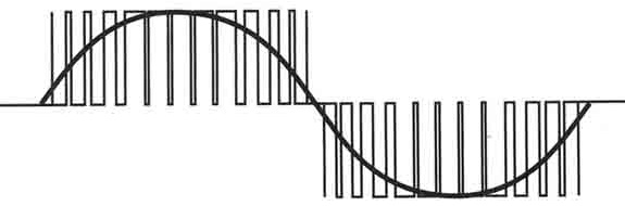
TBD.The output power is a sine wave with a configurable mains frequency (10 to 60 Hz as an example) but laden with spikes or chopped waveform with a carrier frequency of a few kilo-Hz. This is acceptable for standard AC motors, or rather the carrier frequency used in commercially available VFDs is optimized to keep the motors healthy and not to generate any ill-effects, especially high frequency harmonics.
TBD.Output Wavefrom from a VFD
TBD.The same waveform as explained and shown above, is generated in all the three phases of the output, but appropriately phase shifted by 120 degrees from each other. That makes a nice power source for a three phase AC motor.
TBD.During startup the VFD outputs a lower frequency of say 10 Hz and correspondingly lower pulse width (effectively a reduced AC voltage at the output). It is then gradually increased over a period of 5 to 15 seconds to normal operating frequency of 50 Hz. That is how a soft start is implemented.
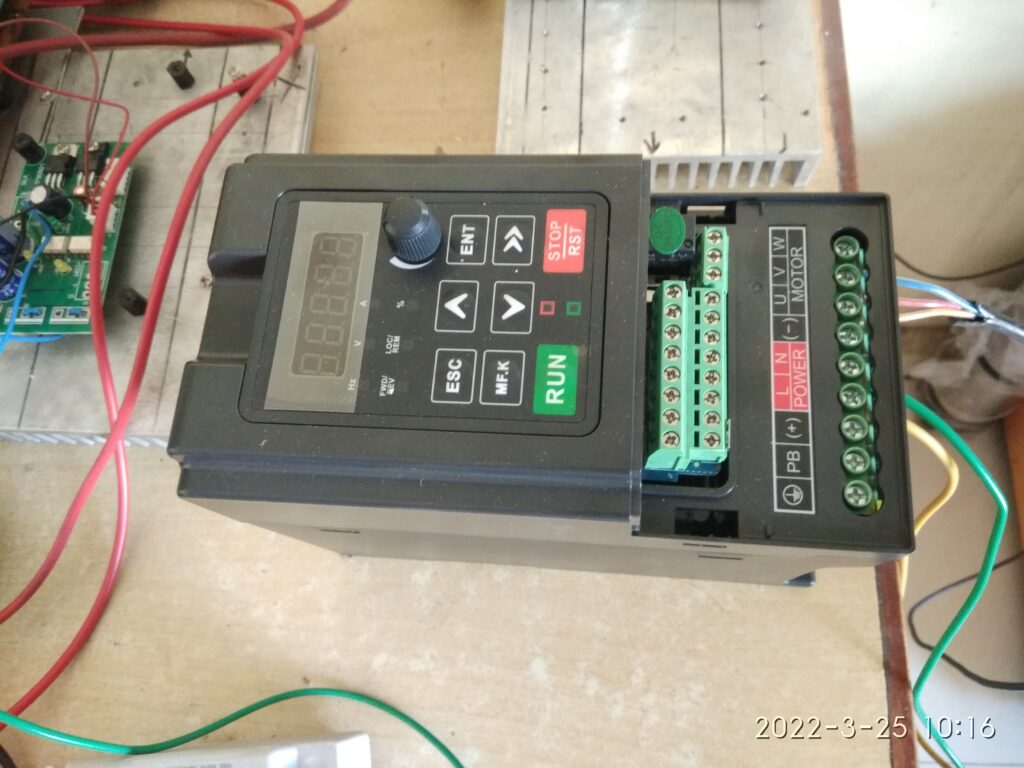
TBD.VFDs have a simple and basic keypad with start, stop, menu buttons. Keypad permits setting of various configurable parameters, and also displays the operating status/errors if any.
TBD.Connectivity with external controlls is also provided, which allows dynamically setting the output frequency and voltage, external start and stop commands etc.
TBD.A fewer brands of VFDs have started manufacturing VFDs with additional features as below.
TBD.Customized phaseshift of 90/110 degrees (instead of 120) between the three output phases, to emulate the 3 wire power supply of a single phase capacitor run motor.
TBD.Changes to output frequency at runtime based on an inbuilt MPPT (maximum power point tracking) algorithm, essential for solar panels.
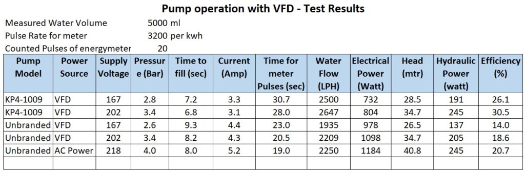
TBD.Test Results
TBD.With the concept explained so far as above, we have carried out a few real life tests using a VFD and borewell submersible pump.
TBD.Equipment used is listed below
TBD.FRECON Make Solar VFD, model number FR150T – 2S – 2.2B -H, this accepts single phase AC input or DC input and gives out 3 phase 220 VAC. Has configuration settings to connect a single phase motor across the three U V W output terminals, and also has a MPPT algorithm in-built into it. It is not a Make In India brand but has ample presence of local dealer network in India. Build wise seems a good robust build.
TBD.Kirloskar make borewell submersible pump model Jalaraj KP4-1009 with 10 stages impeller, single phase 1 HP, 220VAC oil filled motor.
TBD.An unbranded borewell submersible pump, 10 stages, 0.5 HP 220VAC water filled motor, purchased from local market.
TBD.Energy Meter Secure Make, single phase 220VAC 30 Amps, 3200 pulses for 1 KWH unit consumption.
TBD.Power was taken from normal household AC supply
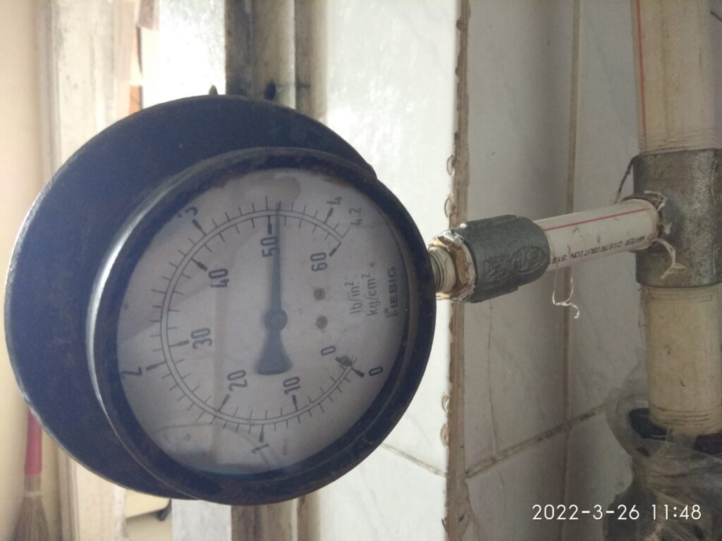
TBD.Water flow and pressure measurement was carried out using conventional simple techniques.
TBD.Normal AC power supply was connected to the input of VFD
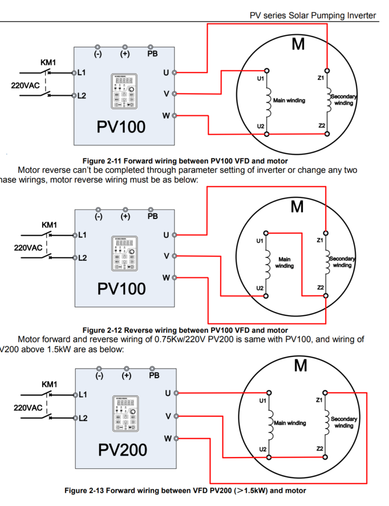
TBD.Output terminals of the VFD were connected to the pump as given in the user guide of the VFD, i.e. TBD.UTBD.>>TBD.YTBD., TBD.VTBD.>>TBD.RTBD., TBD.WTBD.>>TBD.B
TBD.Two different voltage settings were used for testing at 100% and 80% of normal using F00.16 configuration of VFD.
TBD.Valve in the delivery line was kept open in such a way as to be near the operating point to get 2.5 to 3.5 bar pressure and around 1800 LPH flow.
TBD.Below are few images and videos related to the tests carried out.
TBD.Short Video of the Trial Run, shows the simple setup, pump, energymeter and VFDTBD.Frecon VFDTBD.connection diagramTBD.Pressure GaugeTBD.Unbranded 0.5 HP pump, This turned out to be actually a 1 HP pump with much less efficiency than the Kirloskar PumpTBD.Output from VFD visually seen using light bulbs. VFD was configured for a single Phase Motor. This is typical to the FRECON Solar VFD model that they have provided a configuration setting. F08.00 = 2
TBD.Important observations
TBD.The VFD was tried in two different wiring arrangements. TBD.Two wire output modeTBD.: This is as per connection F08.00 = 1, whereby the run capacitor of the motor would be kept in circuit and only two wires of the VFD output were connected to the motor starter. In this case it was seen that the motor draws relatively more current untill it starts rotating and there after settles down to normal operating current. The starting current in this case is not as high as it would be otherwise on normal AC power supply, but still higher than running current. This is expected to be so and likely due to the inadequate capacitance at lower starting frequency. TBD.Three wire output mode:TBD. This is as per connection F08.00 = 2, as shown in figure 2.11 In this case the motor draws steadily and gradually increasing current until it stabilizes to the normal running current. TBD.This is a very important and useful aspect of the connection arrangement supported by this VFD since it will help deployment of optimum capacity of solar panels.
TBD.Further Work
TBD.It is essential to carry out similar tests with input power taken from suitably selected solar panels at various time of the day.
TBD.An online calculator for panel capacity is presented here at the below link. This will be useful to select the panel ratings for a given pump capacity.
TBD.On 30-March-2022 this VFD and 1HP single phase pump was installed at a farm site in Murbad.
TBD.Total of 1600 Watt Solar Panels are used to drive the VFD which is a mixed set as below. TBD.8 x 100 Watt 18 V in series with TBD. ( TBD. ( 4 x 100 Watt 46 V in series ) TBD. x 2 such strings in parallel TBD. )
TBD.It was seen that pump delivers 3000 to 3600 LPH water at about 30 feet total head, panel side voltage found to be in the order of 300 to 330 VDC, the VFD appropriately keeps regulating the output frequency from 35 to 50 Hz in order to maximize the solar energy generation from the panels and the VFD output voltage was seen to be in range of 160 to 220 VAC.
TBD.Long term trial run is planned and results will be published.
TBD.Video of the VFD in operation and solar panels used.TBD.Water flow from the pump
TBD.Centrifugal pumps running on normal AC power supply are very common, fairly efficient and most importantly they are locally available from wide range of manufacturers. Their use and operation is more or less hasslefree, they are easily serviceable at nearby workshops and pricewise also they are affordable. These points are specifically important in comparison to a classical solar pump system that is available in market these days, and which potentially uses a BLDC 3 phase DC motor/pump with permanent magnets and all stainless steel body.
TBD.These standard AC pumps are available in 0.5 HP to 10s of HP of power rating, able to run on single phase (220V) or three phase (415V) AC power supply and available in formats like monoblock pumpset, openwell submersible and borewell submersible pumps.
TBD.Monoblock PumpTBD.Openwell Submersible PumpTBD.Borewell Submersible Pump, motor and pump shown separated from each other.
TBD.This article discusses the use of such standard AC pumps using Solar Panels as the source of electricity.
TBD.Since solar panels generate TBD.DC voltageTBD., it is important to have TBD.some mechanism or deviceTBD. to TBD.convert the DC electricity from the panels to AC powerTBD. so that the pump can run on it.
TBD.A standard AC motor consumes large amounts of current during startup for a few seconds, this current can be 2 to 6 times of the normal operating current at full load. On the other hand solar panels are a TBD.current limited source of powerTBD. i.e. the current output available from a given solar panel is limited by the size of panel. This means that the solar panels which would be sized and selected to meet the current requirements of the pump at normal operating load are not going to be able to start the pump in normal or traditional manner. TBD.Some kind of soft start approach is neededTBD..
TBD.Also based on sunlight available over the day time, the output voltage, current and power from solar panels is going to vary, this needs to be maximized by making the pump run at various voltage and/or AC frequency. The standard AC motor which is expected to operate at 50 Hz power supply, can actually be made to run over a range of supply frequency (35 to 55 Hz) without any significant side effects. In this range of frequency, the output power of the motor varies almost linearly and this inherent feature can be used to match the solar panel output with the pump-motor power requirements.
TBD.All the above leads to a solution which has to be based on some sort of electronics to support following features.
TBD.DC to AC conversion
TBD.Soft start or gradually increasing voltage during startup
TBD.Output voltage and frequency modulation to optimize the power generation from the solar panels.
TBD.For 1 and 2 above there already exists a robust industrial device called TBD.Variable Frequency Drive (VFD)TBD.. VFDs are often used in various industries to control the load and/or speed of standard AC motors which drive the heavy plant and machinery.
TBD.Most VFDs allow AC (single or three phase) or DC power supply as input and generate three phase AC power as output.
TBD.VFD – Variable Frequency Drive
TBD.Internally the input AC power supply is first rectified to DC, that is what makes VFD suitable to run with Solar Panels. Then a microcontroller based circuitry drives a set of power transistors (IGBT or MOSFETs) to achieve DC to AC conversion with a SPWM (sinusoidal pulse width modulation) technique.
TBD.The output power is a sine wave with a configurable mains frequency (10 to 60 Hz as an example) but laden with spikes or chopped waveform with a carrier frequency of a few kilo-Hz. This is acceptable for standard AC motors, or rather the carrier frequency used in commercially available VFDs is optimized to keep the motors healthy and not to generate any ill-effects, especially high frequency harmonics.
TBD.Output Wavefrom from a VFD
TBD.The same waveform as explained and shown above, is generated in all the three phases of the output, but appropriately phase shifted by 120 degrees from each other. That makes a nice power source for a three phase AC motor.
TBD.During startup the VFD outputs a lower frequency of say 10 Hz and correspondingly lower pulse width (effectively a reduced AC voltage at the output). It is then gradually increased over a period of 5 to 15 seconds to normal operating frequency of 50 Hz. That is how a soft start is implemented.
TBD.VFDs have a simple and basic keypad with start, stop, menu buttons. Keypad permits setting of various configurable parameters, and also displays the operating status/errors if any.
TBD.Connectivity with external controlls is also provided, which allows dynamically setting the output frequency and voltage, external start and stop commands etc.
TBD.A fewer brands of VFDs have started manufacturing VFDs with additional features as below.
TBD.Customized phaseshift of 90/110 degrees (instead of 120) between the three output phases, to emulate the 3 wire power supply of a single phase capacitor run motor.
TBD.Changes to output frequency at runtime based on an inbuilt MPPT (maximum power point tracking) algorithm, essential for solar panels.
TBD.Test Results
TBD.With the concept explained so far as above, we have carried out a few real life tests using a VFD and borewell submersible pump.
TBD.Equipment used is listed below
TBD.FRECON Make Solar VFD, model number FR150T – 2S – 2.2B -H, this accepts single phase AC input or DC input and gives out 3 phase 220 VAC. Has configuration settings to connect a single phase motor across the three U V W output terminals, and also has a MPPT algorithm in-built into it. It is not a Make In India brand but has ample presence of local dealer network in India. Build wise seems a good robust build.
TBD.Kirloskar make borewell submersible pump model Jalaraj KP4-1009 with 10 stages impeller, single phase 1 HP, 220VAC oil filled motor.
TBD.An unbranded borewell submersible pump, 10 stages, 0.5 HP 220VAC water filled motor, purchased from local market.
TBD.Energy Meter Secure Make, single phase 220VAC 30 Amps, 3200 pulses for 1 KWH unit consumption.
TBD.Power was taken from normal household AC supply
TBD.Water flow and pressure measurement was carried out using conventional simple techniques.
TBD.Normal AC power supply was connected to the input of VFD
TBD.Output terminals of the VFD were connected to the pump as given in the user guide of the VFD, i.e. TBD.UTBD.>>TBD.YTBD., TBD.VTBD.>>TBD.RTBD., TBD.WTBD.>>TBD.B
TBD.Two different voltage settings were used for testing at 100% and 80% of normal using F00.16 configuration of VFD.
TBD.Valve in the delivery line was kept open in such a way as to be near the operating point to get 2.5 to 3.5 bar pressure and around 1800 LPH flow.
TBD.Below are few images and videos related to the tests carried out.
TBD.Short Video of the Trial Run, shows the simple setup, pump, energymeter and VFDTBD.Frecon VFDTBD.connection diagramTBD.Pressure GaugeTBD.Unbranded 0.5 HP pump, This turned out to be actually a 1 HP pump with much less efficiency than the Kirloskar PumpTBD.Output from VFD visually seen using light bulbs. VFD was configured for a single Phase Motor. This is typical to the FRECON Solar VFD model that they have provided a configuration setting. F08.00 = 2
TBD.Important observations
TBD.The VFD was tried in two different wiring arrangements. TBD.Two wire output modeTBD.: This is as per connection F08.00 = 1, whereby the run capacitor of the motor would be kept in circuit and only two wires of the VFD output were connected to the motor starter. In this case it was seen that the motor draws relatively more current untill it starts rotating and there after settles down to normal operating current. The starting current in this case is not as high as it would be otherwise on normal AC power supply, but still higher than running current. This is expected to be so and likely due to the inadequate capacitance at lower starting frequency. TBD.Three wire output mode:TBD. This is as per connection F08.00 = 2, as shown in figure 2.11 In this case the motor draws steadily and gradually increasing current until it stabilizes to the normal running current. TBD.This is a very important and useful aspect of the connection arrangement supported by this VFD since it will help deployment of optimum capacity of solar panels.
TBD.Further Work
TBD.It is essential to carry out similar tests with input power taken from suitably selected solar panels at various time of the day.
TBD.An online calculator for panel capacity is presented here at the below link. This will be useful to select the panel ratings for a given pump capacity.
TBD.On 30-March-2022 this VFD and 1HP single phase pump was installed at a farm site in Murbad.
TBD.Total of 1600 Watt Solar Panels are used to drive the VFD which is a mixed set as below. TBD.8 x 100 Watt 18 V in series with TBD. ( TBD. ( 4 x 100 Watt 46 V in series ) TBD. x 2 such strings in parallel TBD. )
TBD.It was seen that pump delivers 3000 to 3600 LPH water at about 30 feet total head, panel side voltage found to be in the order of 300 to 330 VDC, the VFD appropriately keeps regulating the output frequency from 35 to 50 Hz in order to maximize the solar energy generation from the panels and the VFD output voltage was seen to be in range of 160 to 220 VAC.
TBD.Long term trial run is planned and results will be published.
TBD.Video of the VFD in operation and solar panels used.TBD.Water flow from the pump
छोटे खेतों की सिंचाई के लिए जहां पानी का स्रोत पास में उपलब्ध है (या तो एक खुला कुआं, तालाब, झील या ऐसा कोई जल निकाय) छोटे पंपों का उपयोग करना और उन्हें सौर पैनलों पर संचालित करना संभव है।
ये पंप अधिकांश शहरों और छोटे शहरों में ऑनलाइन और साथ ही स्थानीय बाजार में उचित मूल्य पर आसानी से उपलब्ध हैं। वे आमतौर पर कीटनाशकों के लिए उपयोग किए जाने वाले बैटरी चालित बैकपैक स्प्रेयर में उपयोग किए जाते हैं।
This post explains some important aspects of this type of pumps for use at small irrigation sites.
यह पोस्ट छोटे सिंचाई स्थलों पर उपयोग के लिए इस प्रकार के पंपों के कुछ महत्वपूर्ण पहलुओं की व्याख्या करता है।
Such a pump is run by a DC motor and has a PVC block head where positive displacement of water is achieved by action of miniaturized pistons inside the block.
ऐसा पंप डीसी मोटर द्वारा चलाया जाता है और इसमें पीवीसी ब्लॉक हेड होता है जहां ब्लॉक के अंदर छोटे पिस्टन की क्रिया द्वारा पानी का दबाव बढाया जाता है।
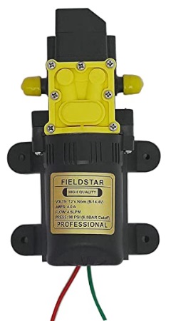
A pump having single motor is often priced at 550 to 650 INR and delivers upto 3 LPM water and claims to generate pressure of 70 PSI or 5 Bar i.e. upto 50 meters of height.
सिंगल मोटर वाले एक पंप की कीमत अक्सर 550 से 650 रुपये होती है और यह 3 लिटर प्रति मिनिट तक पानी दे सकता है और 70 पीएसआई या 5 बार यानी 50 मीटर ऊंचाई तक का दबाव उत्पन्न करने का दावा करता है।
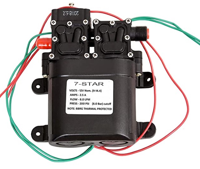
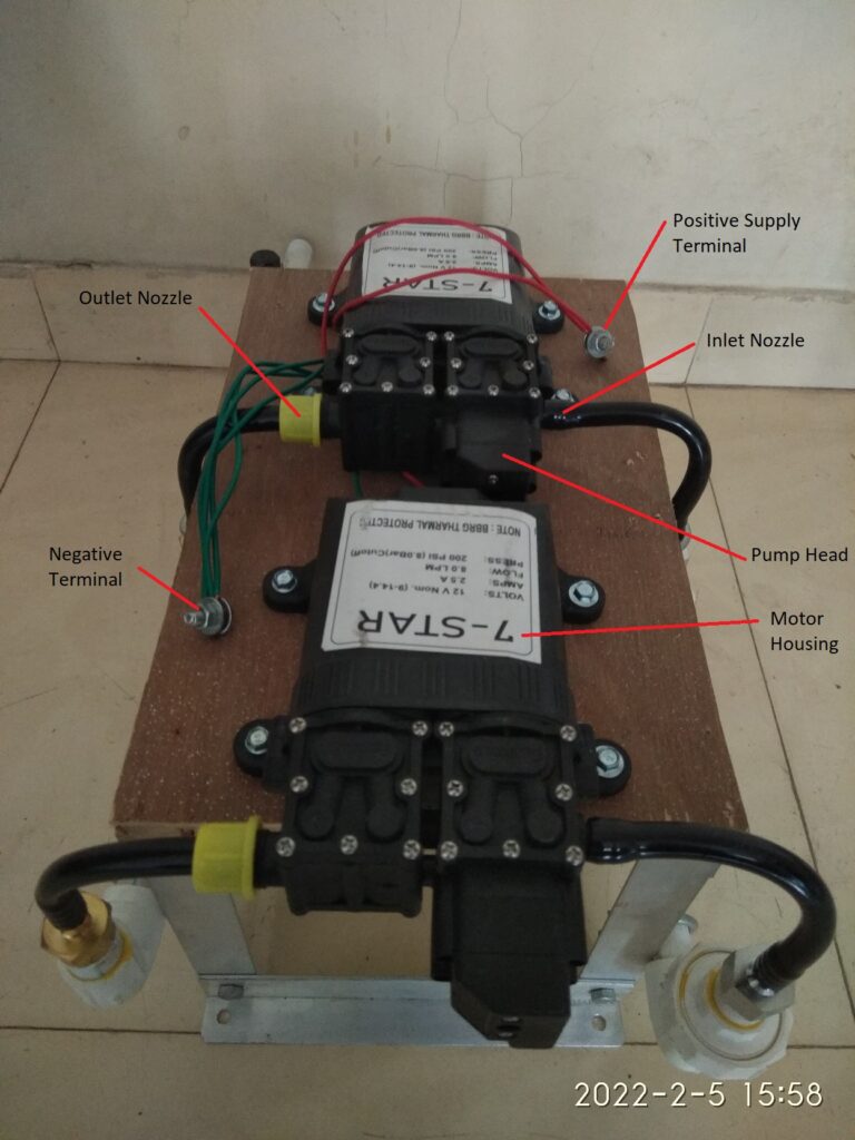
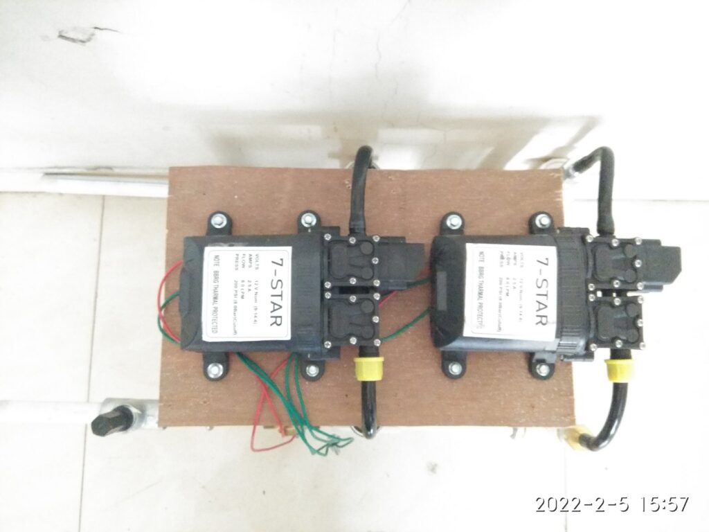
Pump with twin motor is also available and priced at 1000 INR, delivers 5 to 6 LPM of water at similar pressure.
दो मोटर वाला पंप भी उपलब्ध है और इसकी कीमत लगभग 1000 रुपये है, समान दबाव पर 5 से 6 लीटर पानी की आपूर्ति करता है।
Next two images show a single motor and dual or twin motor pump.
अगली दो छवियां एकल मोटर और दोहरी या जुड़वां मोटर पंप दिखाती हैं।
The DC Motor used is a DC motor with brushes and follows a standard specification named as 775 motor, some details can be found here.
The motor can be operated over a wide range of DC supply voltage (6 to 36VDC) but the pump manufacturers normally mark the pump for operation in range of 12 to 14.5 VDC only.
We have installed such pumps at a couple of sites and safely connected to solar panels of 12VDC nominal (or 18VDC MPPT voltage). The motor of the pump nicely works with the electricity generated by solar panel during the daytime. As the intensity of sunlight changes throughout the day, the output flow of water varies and is acceptable for the irrigation purposes.
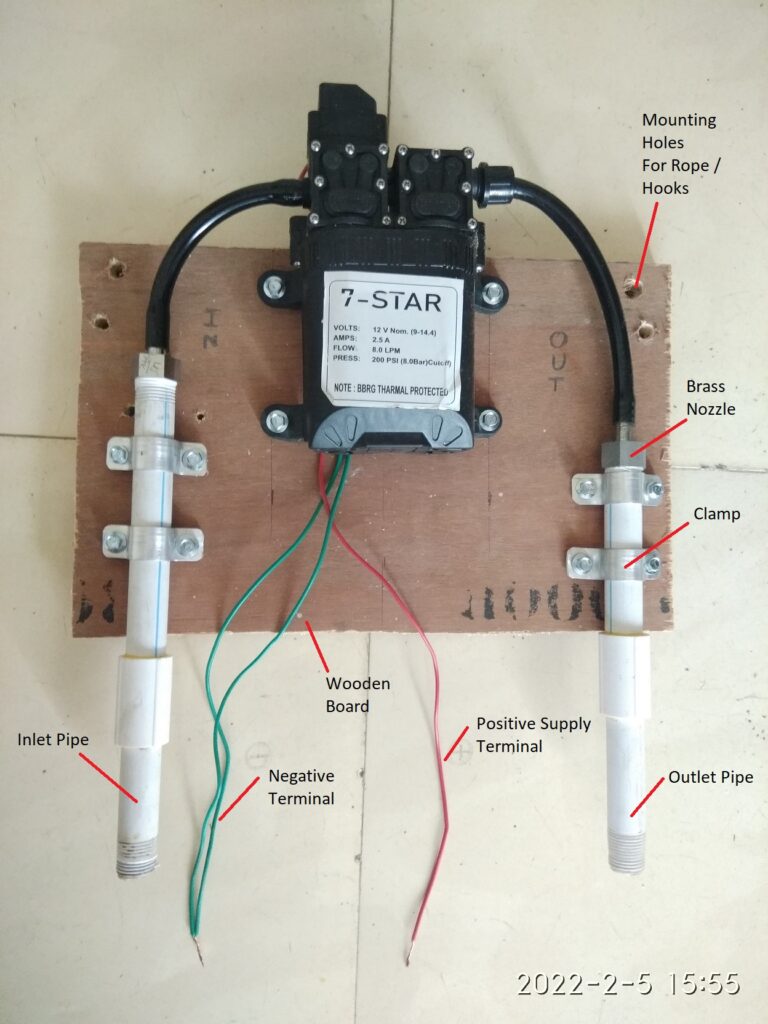
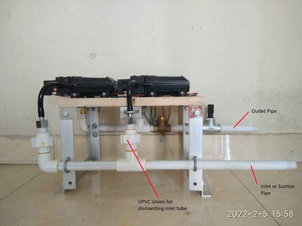
Inlet and outlet of the pump is however a non-standard (or at least not easily available) tubing size. Most suppliers provide a PVC/HDPE tube with threaded PVC nut to attach to the pump outlet nozzle, but the connectors with standard pipe sizes (say 0.5 or 1 inch nominal bore pipe) are difficult to find.
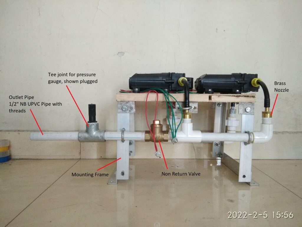
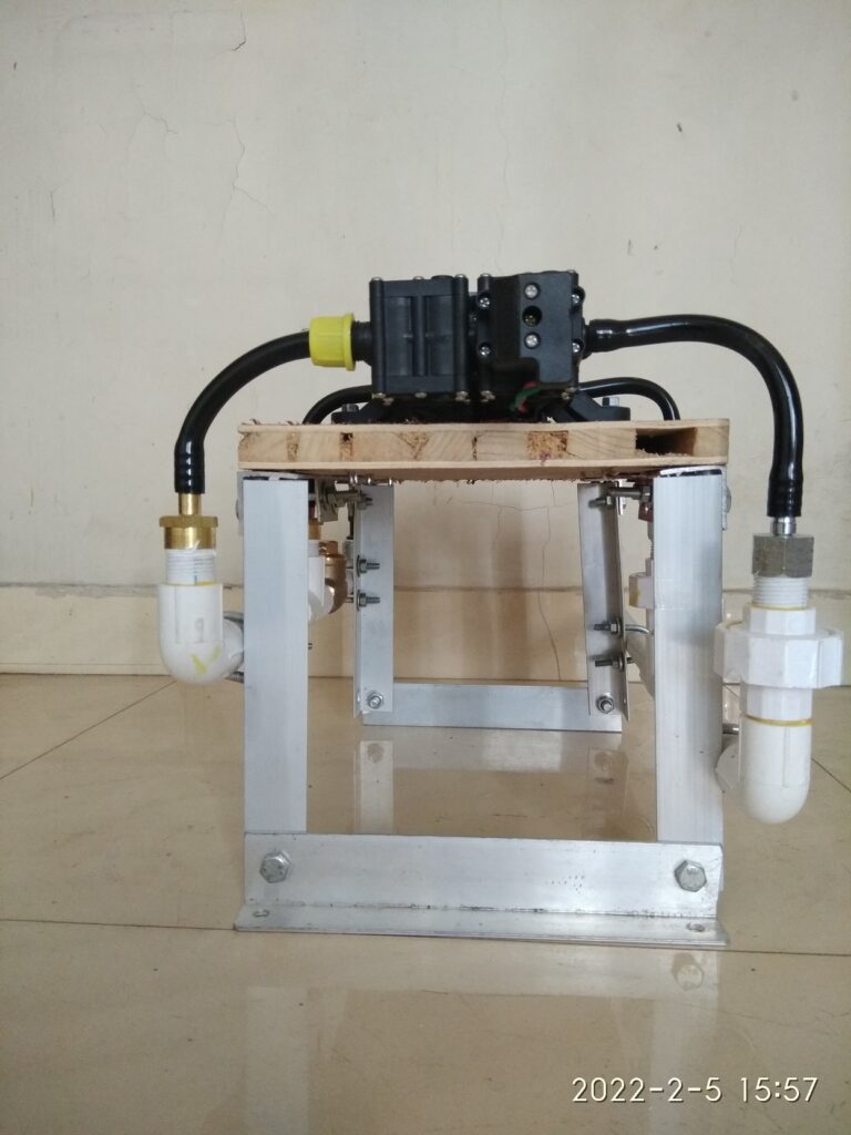
We have used a typical nozzle connection seen in pictures and created a simple skid mounted assembly of this type of pumps, eiether one pump on the skid or 2 on the skid as per the requirements.
With 2 pumps on the skid it is seen that 150 to 200 watt panels are adequate for operation throughout the day. For single pump a panel of 75 to 100 watt is appropriate.
Next few images explain the mounting approach we have used and is only a suggestion. Any suitable alternative can be followed that meets the needs and materials availability at the installation site.
Single Pump Skid
Dual Pump Skid
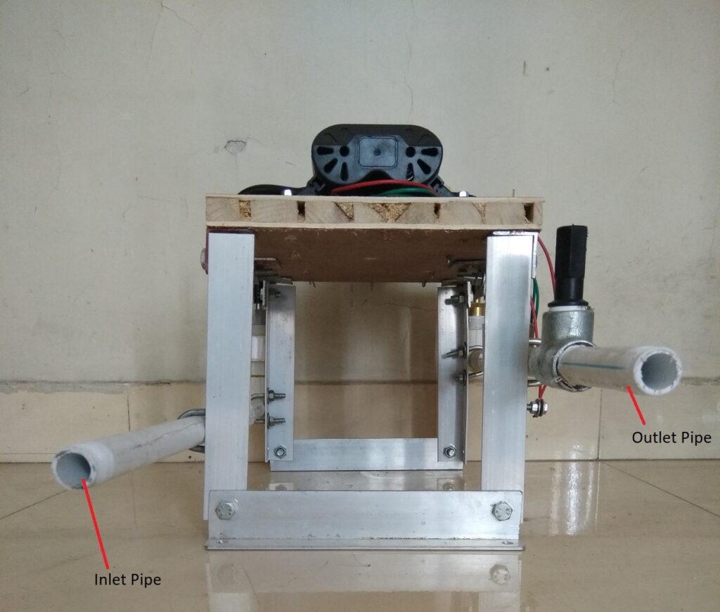
Front view of the pump skid with inlet and outlet pipes on left side.
Seen from top at an angle / 3-D view.
Left Side View
Rear View
Right Side View
Top View
Important Instructions
Pump and motor must never be submerged in water and water must not get into the motor.
DC power supply polarity needs to be correctly followed. Green wires to be connected to negative terminal of the battery or solar panels, and red wire to positive terminal.
DC supply voltage must never exceed 18 volts.
In no case, AC supply / mains supply shall be applied to the motor, it is hazardous besides the fact that it will permanently damage the motor.
Testing of pump without water by supplying DC power for a second or say two seconds is ok, but must not run the motor for longer duration without water.
At the inlet pipe a suitable filter in form of nylon mesh is highly recommended. The internal piston mechanism of the pump is too small to get clogged by smallest of the particles.
This type of pump can generally start from dry run and can self prime in a few seconds, but if it does not do so, please do not run it dry for long time. Instead open the nozzles and check if any clogging or blockages. Try to pull water from outlet nozzle or pipe by sucking the air.
The pump can lift water from upto 5-6 feet on the suction side, however it is better to keep the suction pipe length as small as possible.
It is recommended to install a footvalve at end of the suction pipe submerged inside the water, it is best to attach a filter mesh around the footvalve.
Make sure that the pump skid is mounted on a sturdy platform or base. Alternatively pump can be suspeneded firmly inside an openwell clearly above the water level.
Use solar panels of 12VDC nominal voltage only, any higher voltage panels if connected to the pump will damage the same. It is better to first check the nameplate on the backside of the solar panel before connecting for the first time. The nameplate should read 12VDC nominal and/or 17-18 VDC MPPT or maximum power voltage.
Single pump skid is suitable to operate with 75 to 100 Watt panel and dual pump skid with 150 to 200 Watts. Excessively higher wattage of the solar panels must be avoided.
This type of pump is supposed to be used for intermittent duty only however through our experimentation in actual sites, we find that using the pump every day for 3 to 5 hours is fine.
Connect the outlet pipe with suitable coupling or union with the delivery pipe to be arranged at the site to suit the distance of the final delivery location away from the water source.
Ensure that the inlet and outlet pipe connections do not lead to forces on the pipes or the skid.
If in doubt please reach out to us through email or phone.
जेथे पाण्याचे स्त्रोत जवळपास उपलब्ध आहेत (विहीर, तळे, तलाव किंवा यासारखा कोणताही जलसाठा ) अश्या लहान आकाराच्या शेतीला पाणी देण्यासाठी सौर पॅनेलवर चालणारा छोटा पंप वापरणे शक्य आहे.
हे असे छोटे पंप ऑनलाइन तसेच स्थानिक बाजारपेठेत बहुतांश शहरे आणि लहान शहरांमध्ये वाजवी किमतीत सहज उपलब्ध आहेत. कीटकनाशकांसाठी वापरल्या जाणार्या बॅटरीवर चालणार्या बॅकपॅक स्प्रेअर यंत्रामध्ये असे पंप सामान्यपणे वापरले जातात.
हा लेख अश्या छोट्या प्रकारच्या पंपांबाबतची माहीती मिळावी या हेतूने लिहिला आहे.
Such a pump is run by a DC motor and has a PVC block head where positive displacement of water is achieved by action of miniaturized pistons inside the block.
ऐसा पंप डीसी मोटर द्वारा चलाया जाता है और इसमें पीवीसी ब्लॉक हेड होता है जहां ब्लॉक के अंदर छोटे पिस्टन की क्रिया द्वारा पानी का दबाव बढाया जाता है।
A pump having single motor is often priced at 550 to 650 INR and delivers upto 3 LPM water and claims to generate pressure of 70 PSI or 5 Bar i.e. upto 50 meters of height.
सिंगल मोटर वाले एक पंप की कीमत अक्सर 550 से 650 रुपये होती है और यह 3 लिटर प्रति मिनिट तक पानी दे सकता है और 70 पीएसआई या 5 बार यानी 50 मीटर ऊंचाई तक का दबाव उत्पन्न करने का दावा करता है।
Pump with twin motor is also available and priced at 1000 INR, delivers 5 to 6 LPM of water at similar pressure.
दो मोटर वाला पंप भी उपलब्ध है और इसकी कीमत लगभग 1000 रुपये है, समान दबाव पर 5 से 6 लीटर पानी की आपूर्ति करता है।
Next two images show a single motor and dual or twin motor pump.
अगली दो छवियां एकल मोटर और दोहरी या जुड़वां मोटर पंप दिखाती हैं।
The DC Motor used is a DC motor with brushes and follows a standard specification named as 775 motor, some details can be found here.
The motor can be operated over a wide range of DC supply voltage (6 to 36VDC) but the pump manufacturers normally mark the pump for operation in range of 12 to 14.5 VDC only.
We have installed such pumps at a couple of sites and safely connected to solar panels of 12VDC nominal (or 18VDC MPPT voltage). The motor of the pump nicely works with the electricity generated by solar panel during the daytime. As the intensity of sunlight changes throughout the day, the output flow of water varies and is acceptable for the irrigation purposes.
Inlet and outlet of the pump is however a non-standard (or at least not easily available) tubing size. Most suppliers provide a PVC/HDPE tube with threaded PVC nut to attach to the pump outlet nozzle, but the connectors with standard pipe sizes (say 0.5 or 1 inch nominal bore pipe) are difficult to find.
We have used a typical nozzle connection seen in pictures and created a simple skid mounted assembly of this type of pumps, eiether one pump on the skid or 2 on the skid as per the requirements.
With 2 pumps on the skid it is seen that 150 to 200 watt panels are adequate for operation throughout the day. For single pump a panel of 75 to 100 watt is appropriate.
Next few images explain the mounting approach we have used and is only a suggestion. Any suitable alternative can be followed that meets the needs and materials availability at the installation site.
Single Pump Skid
Dual Pump Skid
Front view of the pump skid with inlet and outlet pipes on left side.
Seen from top at an angle / 3-D view.
Left Side View
Rear View
Right Side View
Top View
Important Instructions
Pump and motor must never be submerged in water and water must not get into the motor.
DC power supply polarity needs to be correctly followed. Green wires to be connected to negative terminal of the battery or solar panels, and red wire to positive terminal.
DC supply voltage must never exceed 18 volts.
In no case, AC supply / mains supply shall be applied to the motor, it is hazardous besides the fact that it will permanently damage the motor.
Testing of pump without water by supplying DC power for a second or say two seconds is ok, but must not run the motor for longer duration without water.
At the inlet pipe a suitable filter in form of nylon mesh is highly recommended. The internal piston mechanism of the pump is too small to get clogged by smallest of the particles.
This type of pump can generally start from dry run and can self prime in a few seconds, but if it does not do so, please do not run it dry for long time. Instead open the nozzles and check if any clogging or blockages. Try to pull water from outlet nozzle or pipe by sucking the air.
The pump can lift water from upto 5-6 feet on the suction side, however it is better to keep the suction pipe length as small as possible.
It is recommended to install a footvalve at end of the suction pipe submerged inside the water, it is best to attach a filter mesh around the footvalve.
Make sure that the pump skid is mounted on a sturdy platform or base. Alternatively pump can be suspeneded firmly inside an openwell clearly above the water level.
Use solar panels of 12VDC nominal voltage only, any higher voltage panels if connected to the pump will damage the same. It is better to first check the nameplate on the backside of the solar panel before connecting for the first time. The nameplate should read 12VDC nominal and/or 17-18 VDC MPPT or maximum power voltage.
Single pump skid is suitable to operate with 75 to 100 Watt panel and dual pump skid with 150 to 200 Watts. Excessively higher wattage of the solar panels must be avoided.
This type of pump is supposed to be used for intermittent duty only however through our experimentation in actual sites, we find that using the pump every day for 3 to 5 hours is fine.
Connect the outlet pipe with suitable coupling or union with the delivery pipe to be arranged at the site to suit the distance of the final delivery location away from the water source.
Ensure that the inlet and outlet pipe connections do not lead to forces on the pipes or the skid.
If in doubt please reach out to us through email or phone.