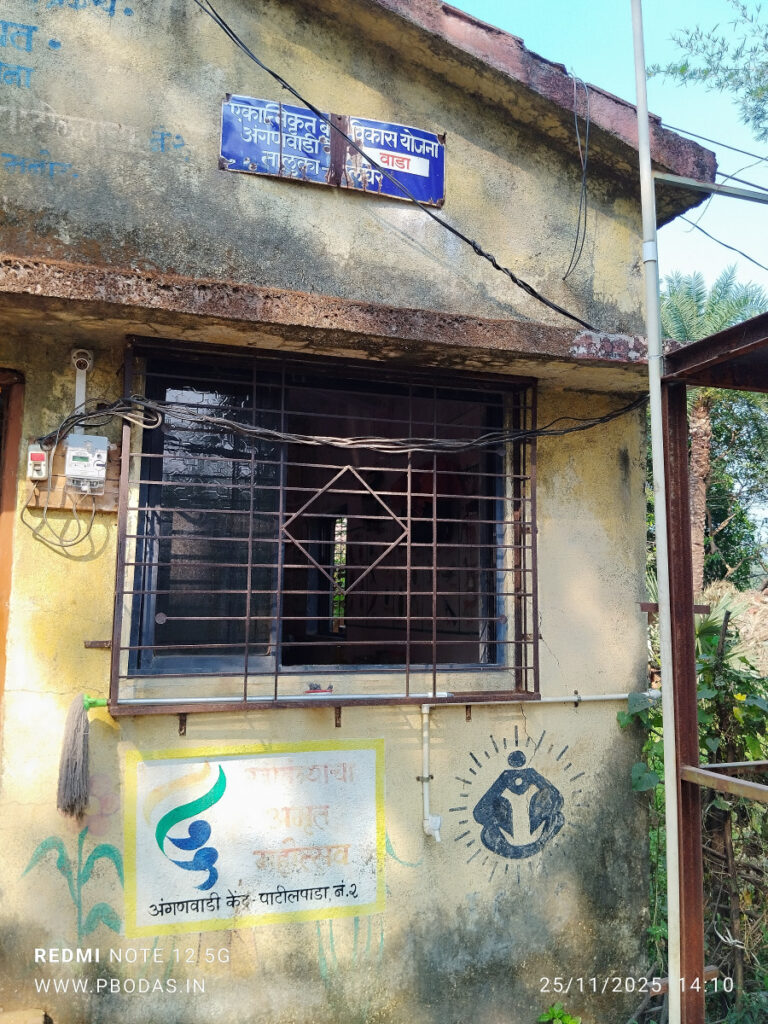
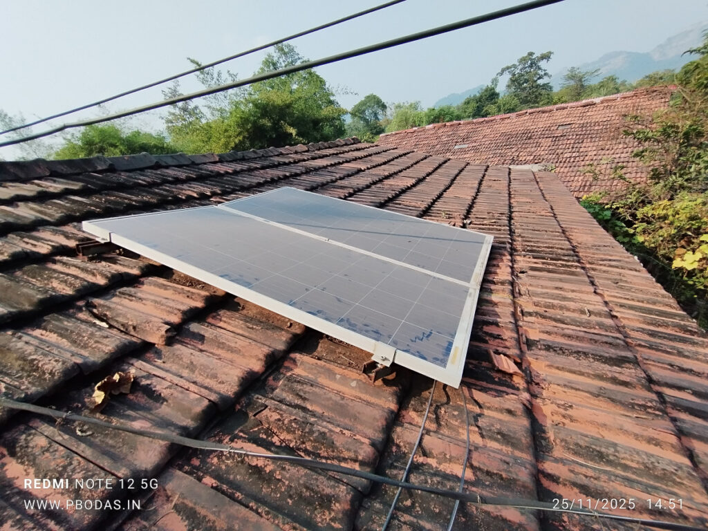
सूर्यप्रकाशाच्या वेळेत माफक वीज वापर करायचा आहे अशा ठिकाणी… जिप शाळांसाठी… लहान शाळांसाठी… अंगणवाडी केंद्रांसाठी… जिथे केवळ 10, 15, 20 विद्यार्थी… एक किंवा दोनच शिक्षक… एक किंवा दोनच वर्ग खोल्या… त्यात दिवा, पंखा (कमी वीज खाणारा रीमोटवाला BLDC असल्यास उत्तम) आणि असला तर टीव्ही… प्रोजेक्टर नको… पाण्याचा पंप नको… खूप मोठ्या आकाराचा टीव्ही नको… वीज कंपनीची (महावितरण/टोरेंट) वीज नाही… सोलर पॅनल नुसतीच बसवली आहेत पण वापरात नाहीत… महावितरणची वीजजोडणी घेण्यासाठी आणि त्यानंतर दरमहा बिल भरण्याचा खर्च परवडत नाही…
महावितरणकडून नवी वीजजोडणी घेण्यासाठी (एक किलोवॅट मंजूर भार) 4500 ते 5500 आरंभीची रक्कम भरावी लागते आणि त्यानंतर शाळांसाठीच्या वीजदरानुसार दरमहा किमान 450 रुपये बिल येणार.
अशा शाळांसाठी उपयुक्त पर्याय ठरेल असे एक उपकरण बनवले आहे.
थोडक्यात काय तर ज्या ठिकाणी सोलर पॅनल उपलब्ध आहेत आणि दिवसाच्याच वेळात कमी प्रमाणात वीज वापर करायचा असतो तिथे हे खूप सोयीचे ठरेल.
नक्की कसे चालते ?
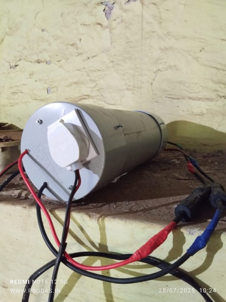
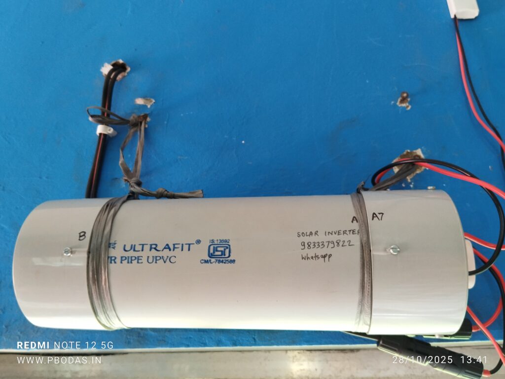
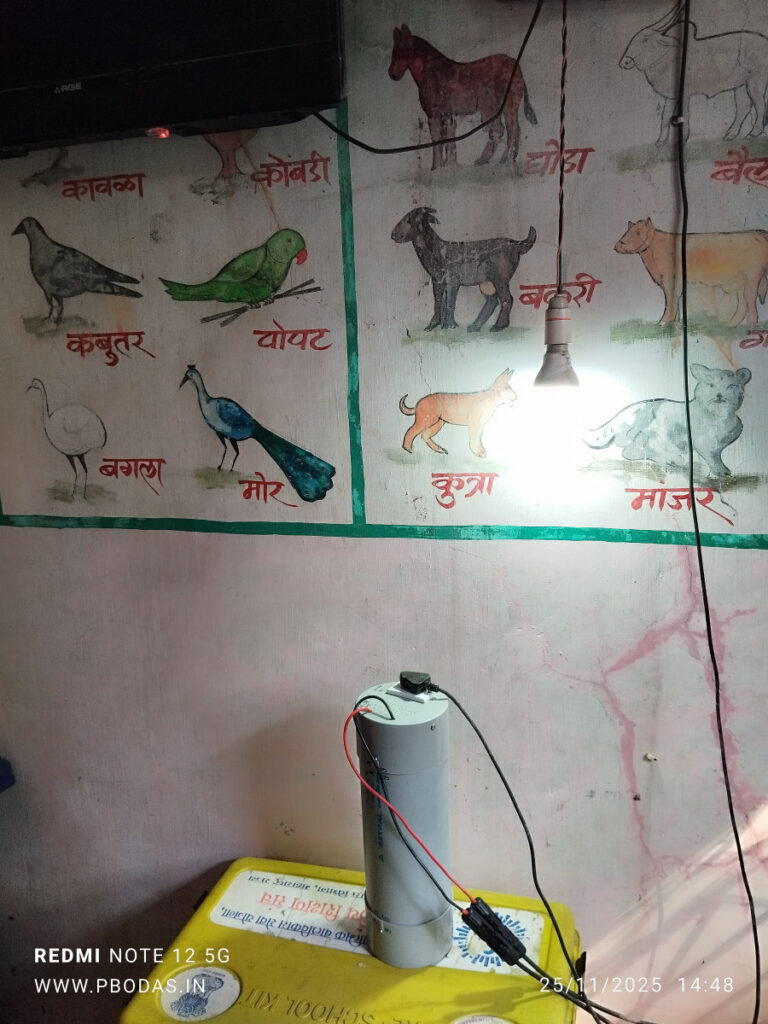
हे उपकरण दिवसाच्या वेळात सूर्यप्रकाशातून निर्माण होणारी सोलर पॅनल मधील वीज (DC) वापरून शाळेतील उपकरणे चालवता येतील अशी वीज (AC) निर्माण करून देते. एका प्रकारचा विना बॅटरी, विना वीजजोडणी चालणारा सोलर पॅनल वर आधारित, मर्यादीत क्षमतेचा इन्व्हर्टर.
हे काही नव्यानेच/प्रथमच बनवले गेले आहे किंवा असे उपकरण अन्यत्र मिळत नाही असे काही नाही. काही कंपन्या अशी उपकरणे / इन्व्हर्टर बनवतात आणि बाजारात विकतात सुद्धा. काही संस्थांमार्फत असे इन्व्हर्टर शाळांना दिले सुद्धा गेले आहेत.
वीजेसंबंधित प्राथमिक तत्वे + इलेक्ट्रॉनिक्स डीझाईन करून त्याप्रमाणे सर्किट बोर्ड तयार करून हे उपकरण स्वतः बनवलेले आहे. म्हटले तर प्रायोगिक आहे परंतु काही शाळांमध्ये बसवून झाले आहे, आणि २८-जुलै-२०२५ पासून वापरात आहे व व्यवस्थित चालते आहे. यासाठी वापरलेल्या सामग्रीची किंमत अंदाजे 4000 रुपये इतकी आहे + जुळणीचा खर्च.
शाळेसाठी काहीतरी करता येत आहे म्हणून मी या इंव्हर्टरची किंमत घेत नाहीये, जि.प. शाळेसाठी म्हणून विनामूल्य बसवून देतो आहे.
किती शाळांना असे विनामूल्य देता येईल? सांगू शकत नाही, परंतु सध्यातरी पाच ते आठ शाळांना असे विनामूल्य देऊ शकेन असे वाटते.
आपल्याला हे उपकरण आपल्या शाळेसाठी योग्य वाटत असेल आणि बसवून घेण्याची इच्छा असेल तर कृपया संपर्क साधावा.
ज्यांना हा इन्वर्टर बसवून घ्यायची इच्छा आहे आणि वर लिहिलेल्या निकषांमध्ये बसत असाल तर या लिंक मध्ये आपल्या गुगल लॉगिनने जावे आणि विचारलेल्या सर्व प्रश्नांची (mandatory आणि optional) उत्तरे भरून सर्व माहिती सबमिट करावी.
एकत्रितपणे सुमारे 100 ते 150 वॅट इतकीच उपकरणे यावर सलग वापरली जाऊ शकतात.
पाच ते दहा मिनिटांसाठी जास्तीत जास्त 200 वॅट इतकी वीज यातून वापरता येईल.
यामध्ये साधे एलईडी बल्ब,एलईडी ट्यूबलाईट, एक साधा पंखा किंवा दोन बीएलडीसी पद्धतीचे कमी वीज खाणारे पंखे आणि एक छोटा ते मध्यम आकाराचा टीव्ही चांगला सूर्यप्रकाश असेल तेव्हा चालू शकतात.
कमी सूर्यप्रकाशात फक्त दिवा आणि कदाचित टीव्ही चालू शकेल.
या इन्व्हर्टरने पाण्याचा पंप किंवा प्रोजेक्टर यासारखी मोठ्या प्रमाणावर वीज खाणारी विद्युत उपकरणे कधीही चालवू नयेत.
कुठल्याही वेळी या इन्व्हर्टरने चालू असलेली उपकरणे जर उपलब्ध सूर्यप्रकाशाच्या तुलनेत जास्त वीजवापर करू पाहतील तर हा इन्व्हर्टर आपोआप बंद पडेल, आणि त्यावर चालू असलेली सर्व उपकरणे बंद होतील. तीस सेकंदांच्या कालावधीनंतर इन्व्हर्टर पुन्हा एकदा उपकरणांना वीजपुरवठा सुरु करेल . त्यावेळी जर सूर्यप्रकाश पुरेसा वाढला असला किंवा काही उपकरणांची बटणे बंद करून ठेवली असली तर वीजपुरवठा सुरळीत सुरु राहील, अन्यथा पुन्हा बंद होईल. या इन्व्हर्टरला वीजसाठा करण्याची सोय / बॅटरी नसल्याने उपलब्ध सूर्यप्रकाशानुसार शक्य तेवढीच उपकरणे चालू शकतात.
या इन्व्हर्टरची वीज आणि महावितरणची वीज कधीही/ चुकून सुद्धा मिक्स/एकत्र व्हायला नको. तसे झाल्यास एक तर हा इंव्हर्टर डॅमेज होईल आणि नादुरुस्त होऊन जाईल, तसेच शॉर्टसर्किट सारखा प्रकार देखील होऊ शकतो. त्यामुळे महावितरणची वीज पूर्णपणे स्वतंत्र ठेवायची किंवा ती शाळेत नसलेलीच चांगली.
या इन्व्हर्टरला जोडण्यासाठी सोलर पॅनलच्या मागून बाहेर पडणाऱ्या वायर विशिष्ट प्रकारे पॅरलल जोडणीत करून घ्याव्या लागतात आणि त्या तशा असताना काही प्रॉब्लेम नाही.
परंतु भविष्यात सोलर पॅनलचा वापर जर दुसऱ्या कुठल्या कामासाठी करायचा म्हणून हे वायरिंग बदलायची वेळ आली तर सर्वप्रथम हा इन्व्हर्टर वायर सोडवून बाजूला काढून ठेवायचा. सोलर पॅनलचे वायरिंग बदलल्यामुळे या इन्व्हर्टरला डॅमेज होऊ शकतो.
हा इन्व्हर्टर कुठे दिला आहे?
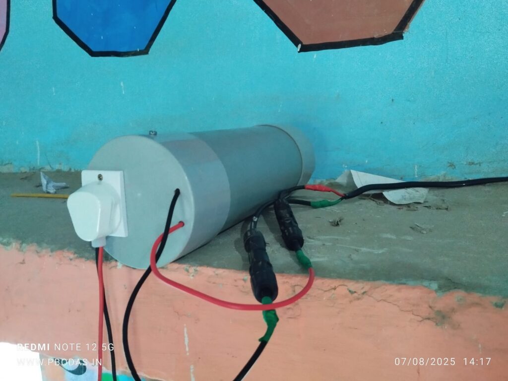
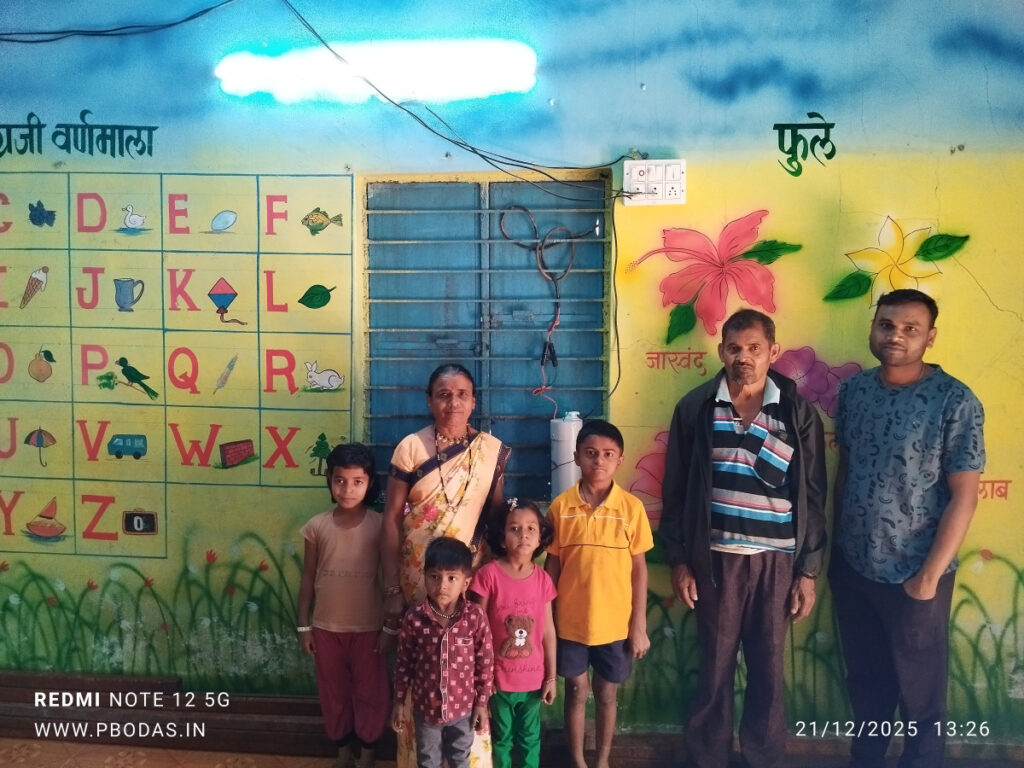
या लेखाच्या सुरुवातीला पाहू शकता, आतापर्यंत बऱ्याच ठिकाणी हा इन्व्हर्टर वापरला जातो आहे.
क्षणचित्रे
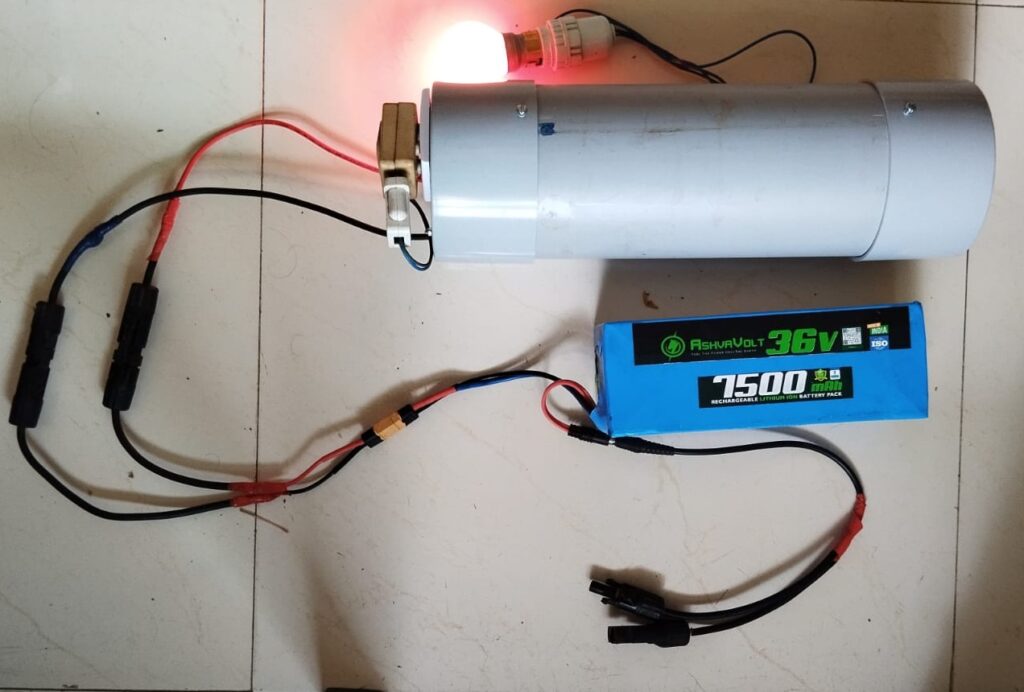
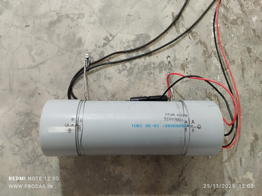
या लेखातील इन्व्हर्टर /उपकरण प्रत्यक्ष इथे पहा. उत्पादनखर्च शक्य तितका कमी व्हावा म्हणुन सहज उपलब्ध असलेल्या पीव्हीसी पाईपचा वापर करून बनवले आहे.
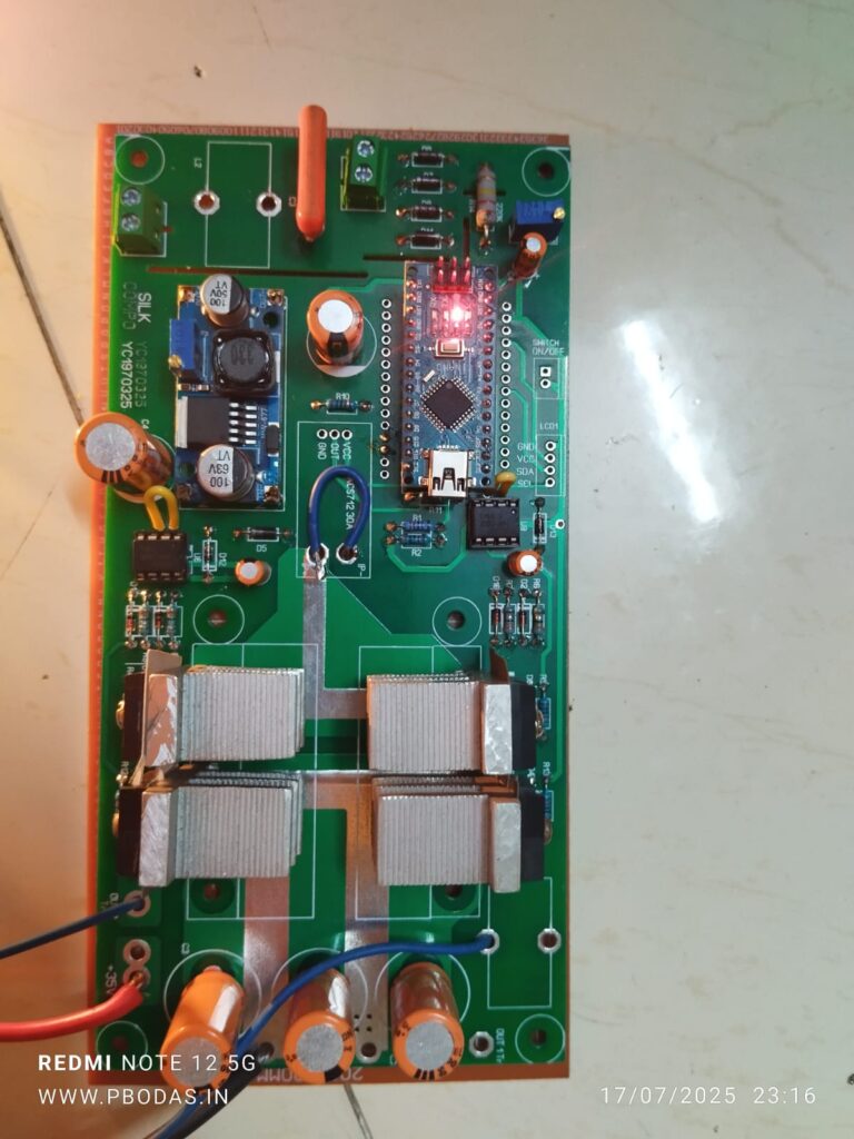
उपकरणामधे वापरलेला सर्कीट बोर्ड
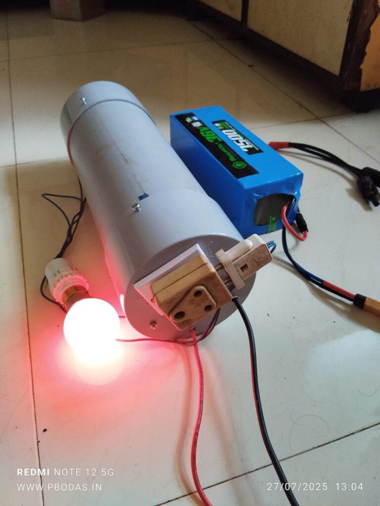
या चित्रात दिसणारी बॅटरी केवळ टेस्टींग/चाचणी साठी वापरली आहे. इन्स्टॉलेशनच्या ठिकाणी हे उपकरण थेट 36VDC सोलर पॅनल सोबत जोडायचे असते.
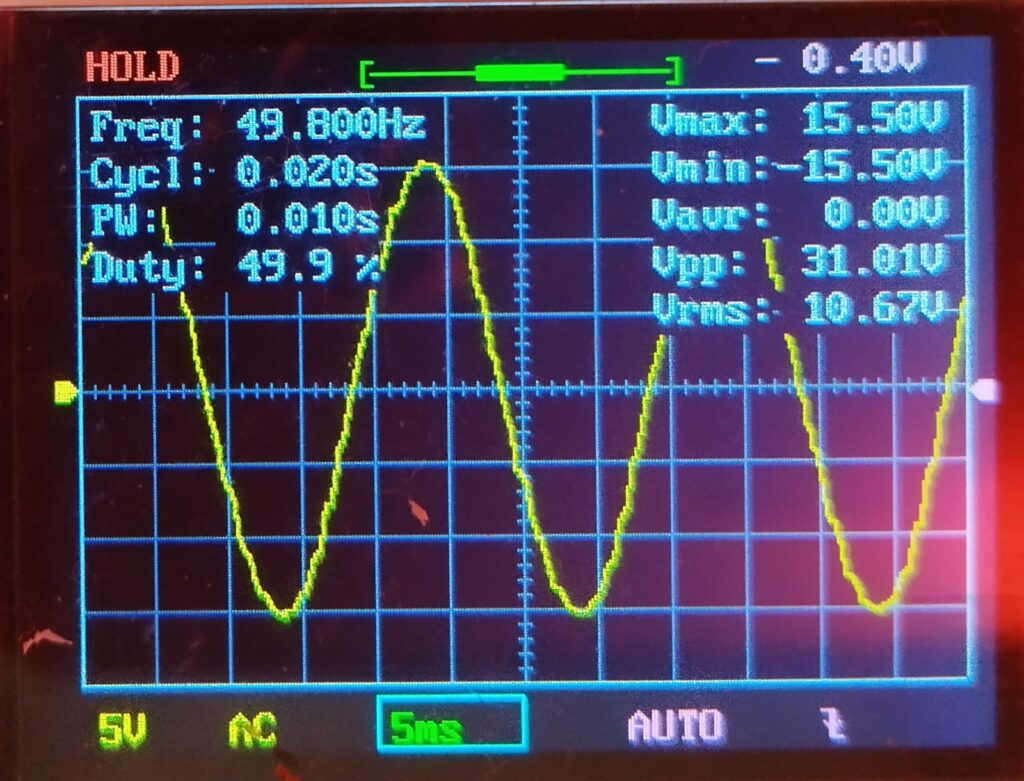
उपकरणाच्या आऊटपुट सॉकेट मधून मिळणारी वीज ही महावितरणच्या वीजेसारखीच Standard 50 Hz Sine Wave वाली असते.
मुंबई नाशिक हायवेवरुन वासिंदला उजवीकडे वळले की रेल्वेलाईन व नंतर नदी ओलांडून अरूंद रस्ता वळणावळणांनी फिरत जातो, वाटेत शेई-शेरी गावाच्या खुणा, चौक लागतात, क्वचित एखादे श्रीमंती पण विना वावर ओस दिसणारे फार्म हाउस.
शहापूरच्या भेट दिलेल्या बऱ्याच शाळांसाठी जो सरळसोट अन् प्रशस्त शहापूर किन्हवली रस्ता परीचयाचा झाला आहे, त्यामानाने हा रस्ता तसा निबीड म्हणावा लागेल.
तर शेरी पुढे नव्याने मोठ्या प्रमाणावर बांधकाम सुरू असलेल्या समृद्धीमार्गापल्याडही जावे लागते आणि मग तंटामुक्त च्या दिमाखदार कमानीतून पुढे जाऊन मासवणे गाव लागते. दाटीवाटीने वसलेली ५०-६० घरे असावीत, आणि त्यातून वाट काढत पुढे जि प शाळा समोर दिसते.
एकंदर तीन इमारतीत पसरलेल्या, उंच-सखल दगडी कातळाच्या जागेवर वसलेल्या शाळेसमोरच्या वाटेत आपले टणक टोकेरी अस्तित्व दाखवणारे खडक अजूनही आहेत, प्रथमदर्शनी मला जाणवले नाहीत तरी त्यातला एक खडक कारच्या तळाला स्पर्शून गेलाच.
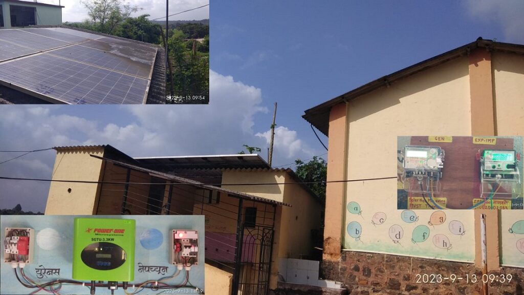
या शाळेत ४-५ वर्षांपूर्वी बसवलेली २५० वॅटची ८ सोलर पॅनल बॅटरी सिस्टीमला जोडली आहेत, आणि अजूनही वापरात आहेत. ३ पैकी २ इमारतींना यातून दिवे आणि २ पंखे शाळेच्या वेळात चालण्याइतपत सौरवीज पुरेशी होते. तर तिसऱ्या इमारतीला मेडा चे ३०० वॅट ची तीन पॅनल आणि स्वतंत्र इन्व्हर्टर बसवला आहे.
याच इमारतीत महावितरणचा वीज मीटरसुद्धा आहे. या इमारतीमागे स्वच्छतागृहाच्या सिमेंट पत्र्याच्या छतावर सोयोची ८ पॅनेल्स एका लोखंडी फ्रेमला बसविली आहेत. ही फ्रेम मात्र छताच्या पत्र्यावर नुसती स्वतःच्या वजनाने ठेवली आहे आणि तारांनी जुजबी बांधली आहे.
पॅनल अशी ठेवली आहेत की त्यांचे पॅरलल वायरींग बदलून सिरीजमध्ये बदलण्यासाठी ८ पैकी ४ पॅनेलच्या जंक्शनबॉक्सला पोहोचताच येईना.
दुसरीकडे शाळेला महावितरणचा वीजपुरवठा काही महिन्यांपूर्वीपासुन सुरु करून घेतलेला आहे आणि त्याचे नियमित ४००+ बिल येऊ लागले आहे. सध्या तरी शिक्षकच आपापसात पैसे जमा करून बिल भरतात. वीजपुरवठा मात्र, नक्की किती ते ना सांगता येण्याइतका, बऱ्याचदा खंडित होत असतो.
गोंधळी मॅडमसोबतच्या संवादातून महाजन साहेबांनी मालती वैद्य स्मृती ट्रस्टतर्फे या शाळेसाठी नेट मीटरींग करून देण्याचा प्रकल्प मंजूर तर केला पण हे असे काही मुद्दे प्रत्यक्ष साईटला भेट देऊनच समोर आले.
त्यातच सोलर अर्जाला महावितरणकडून मान्यता मिळाल्यावर मी इंस्टॉलेशनसाठी दिवस ठरवायला फोन केला असता असे कळले की मॅडमची आता दुसऱ्या शाळेत बदली झाली आहे आणि म्हणून त्यांनी पाटील सरांचा नंबर दिला.
ठाणे-कल्याण परिसरात नाशिक हायवेला नित्याच्या वाहतुकगर्दीच्या भीतीने लवकर निघून मी सव्वानऊवाजता शाळेत पोहोचलो तेव्हा विद्यार्थी आणि शिक्षक यायचे होते.
ते येईपर्यंत मी सर्व निरीक्षणे करून काही आडाखे बांधले. पाटील आणि दळवी सर आल्यावर त्यांच्याशी बोललो आणि नककी काय-कसे करावे यासाठी अर्थातच महाजन साहेबांना फोन लावला.
एकीकडे बिलातून सुटका हवी, दुसरीकडे बॅटरीवाली सिस्टिम चालू राहिल्यास वीजपुरवठा खंडित होईल तेव्हा शाळेसाठी चांगले. वीजपुरवठा जास्त वेळ खंडित होत असेल तर नेटमीटरींग तितकेसे किफायतशीर ही होणार नाही, आणि शिवाय ८ पैकी ४ पॅनल चे वायरींगच बदलता येऊ शकत नाही.
तर मग असे ठरले की ८ पैकी ४ पॅनल नेट मीटरींगला जोडावी, ४ पॅनल बॅटरीलाच जोडली राहू देत. आणि पुढे सोलर मीटरची जोडणी झाल्यापासून ३-४ महीन्यांमध्ये पुढचे कसे ते ठरवता येईल.
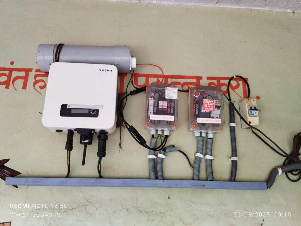
मग यानुसार कामाला गती दिली. दळवी सरांनी मोलाचे सहकार्य केले, एका विद्यार्थ्याच्या साहाय्याने ४ पॅनलचे वायरींग हवे तसे करून घेतले. ग्रीड टाय इन्व्हर्टर, एसीडीबी, डीसीडीबी बसवले. दळवी सरांच्या मताने मीटरसाठी सोयीची जागा ठरवून त्याची फळी बसवली.
आणि प्राथमिक चाचणी करून झाली देखील. १ किलोवॅटची पॅनल जोडली असताना काहीश्या ढगाळ वातावरणात इन्व्हर्टर १७० ते २०० वॅट वीजनिर्मिती दाखवू लागला.
जेवणाची वेळ झाली तसे शिक्षकांसोबत डबा घेऊन बसलो. जवळपास सर्वच शाळांमध्ये जेवणाच्या टेबलवर ओळखी होतात, गप्पा होतात, जिव्हाळ्याचे विषय चर्चेला असतात – त्याबाबत समजते. खात्रीशीर असे दोन मुद्दे हमखास येणार…. १. शाळेत नोकरीसाठी येताना करावे लागणारे प्रवासाचे सायास. २. शाळेच्या कामाव्यतिरीक्त कराव्या लागणाऱ्या योजनांची विवंचना.
जेवणाच्याच वेळेत शाळेला मध्यान्ह भोजनाचे धान्य देणारा टेम्पो आला. त्याबाबतच्या काही बाबी समजल्या. ग्रामपंचायतीकडून वाय-फाय योजनेसाठी शाळेमध्ये सामग्री येऊन पडली आहे परंतु त्याची अजून जोडणी केली नसल्यामुळे नुसतेच जागा अडवून पडले आहे. तीन पैकी एका इमारतीची दुरवस्था झाल्याने पुनर्बांधणीचा प्रस्ताव दिल्याला बरेच दिवस झाले, पण अजून कार्यवाही नाही. चार जणांपैकी पैकी एक शिक्षिका तात्पुरत्या स्वरूपात त्यांच्या नेहमीच्या शाळेऐवजी इथे येतात. असे बरेच काही. असो.
जेवण झाल्यानंतर अर्थिंगचा खड्डा घेऊन त्याची जोडणी पूर्ण केली आणि दळवी सरांना सिस्टीम कशी चालते, मीटरचे रीडिंग कसे घ्यावे, याबाबत शक्यती सर्व माहिती दिली. पुढील प्रक्रियेसाठी माझ्या बाजूने काय करायचे आणि त्यांनी शहापूर महावितरणला जाऊन टेस्टिंगसाठी मीटर देण्याचे समजावून सांगितले.
आवरते घेईतो मुलांनी गलका केला, त्यांचा आता बहुतेक खेळाचा तास सुरू होणार होता. त्यांच्यासोबत यथेच्छ फोटो काढले. शाळेच्या मैदानात ध्वजस्तंभापाशी सकाळी शांत बसून असलेली कुत्र्याची दोन गोजिरवाणी पिल्ले आता चहुकडे बागडत होती. त्यांची आपापसात चाललेली मस्ती आणि शाळेच्या मुलांचा मैदानातला दंगा, बाल्यावस्थेचे रूप एकसारखेच की…
सकाळच्या सारखाच पुन्हा एकदा सरांनी चहा आणवला. बिन दुधाचा आणि बहुतेक गुळाचा केलेला तो कोरा चहा. एक वेगळाच छान स्वाद.
गाडी काढावी तर मुलांनी गाडीतून फिरवून आणण्याचा हट्ट केला, आणि शिरले की आठ दहा जण आत मध्ये… मग दळवी सरांनी थोडा धाक दाखवीत त्यांना बाहेर काढले आणि मी निघालो.
वाटेत भर रस्त्यात एक दीड फुटी साप, थोड्याच वेळापूर्वी अंगावरून गाडीचे चाक गेल्यामुळे असेल, तडफडत होता. कुतूहलापोटी उतरून जवळून पाहिले खरे, परंतु फारसे करता येण्याजोगे सुचले तरी काहीच नाही.
परतीच्या वाटेवर पुढे समृद्धी मार्गाच्या अजस्त्र कामाचा थोडा वेळ थांबून आवाका समजून घेण्याचा प्रयत्न केला, काही फोटो काढले. ठाण्यापर्यंतचा प्रवास नेहेमीपेक्षा तुलनेने बराच वेगात आणि विना अडथळा वापर पडला. घरी आल्यावर मीटर टेस्टिंगची फी भरून पावत्या सरांना पाठवल्या, कमिशनिंग रिपोर्ट आणि सिस्टीम फोटो महावितरणच्या ऑनलाईन वर अपलोड करून दिले.
तर अशाप्रकारे मासवणे शाळेच्या सोलर नेट मीटरिंग ची उभारणी पूर्ण झाली, आता यथावकाश सोलर मीटर बसवून शाळेला प्रत्यक्ष लाभ मिळू लागेल. त्यांच्याकडे आता दोन बॅटरी वाल्या सिस्टीम आणि तिसरी नेट मीटरिंग सिस्टीम असे थ्री इन वन झाले आहे
We have been experimenting with VFDs to run conventional AC Pumps using DC power of solar panels as in previous post (HP Size Solar Pumps) This is because there are a couple of good quality Solar MPPT VFDs easily available at fair prices.
However the VFD requires relatively high DC input voltage, 290 to 360VDC to run a single phase AC pump, and 440+VDC to run a three phase pump.
At sub-HP power levels the solar panels in commercially available sizes (250 to 330 Watt and 36 to 44 VDC each) are most often not going to add up to the input voltage requirements even for a VFD that will run a single phase AC pump.
To deal with this issue, there is a thought process that some kind of DC to DC boost converter can be used from low voltage DC source to raise the DC voltage in the acceptable range for to the VFD.
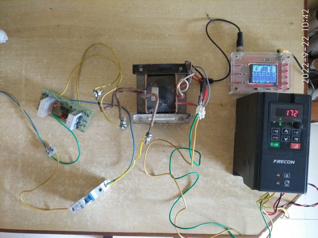
As a quick check a small experiment was carried out involving following components.
DC source from 8 x 60 W 36VDC array of panels but on a fully cloudy day. The open circuit voltage at the panel output was around 24 to 34 VDC.
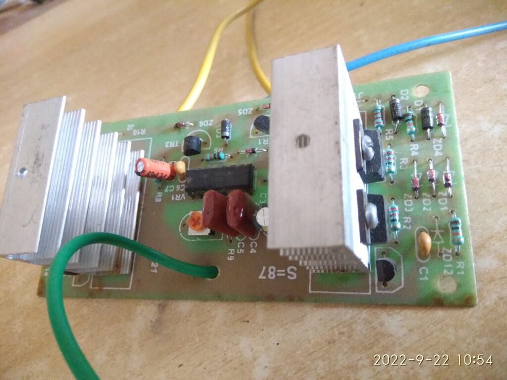
A low cost inverter board that runs on SG3524 chip and MOSFETs, it produces approximately 50 Hz square wave AC output.
3. Salvaged transformer from a household inverter, 12-0-12V to 230V centre tapped, this is rated for around 700VA.
4. Frecon make solar VFD for single phase AC output.
The overall assembled setup is shown in the next picture.
To measure the output voltage and to view the wave pattern, a hobbyst’s oscilloscope (DSO138) was used. At the high voltage side output of the transformer a voltage divider comprising of 22kohm, 1.6kohm and 22kohm was connected. The measuring probes of the oscilloscope were connected across the central 1.6kohm resistor, thus the voltage measured on the oscilloscope is scaled down by a ratio of 1.6 : 44 (i.e. 1 : 27.5). Or in other words, the measured voltage on oscilloscope need to be multipled by 27.5 to get the actual voltage level at the transformer output.
Observations
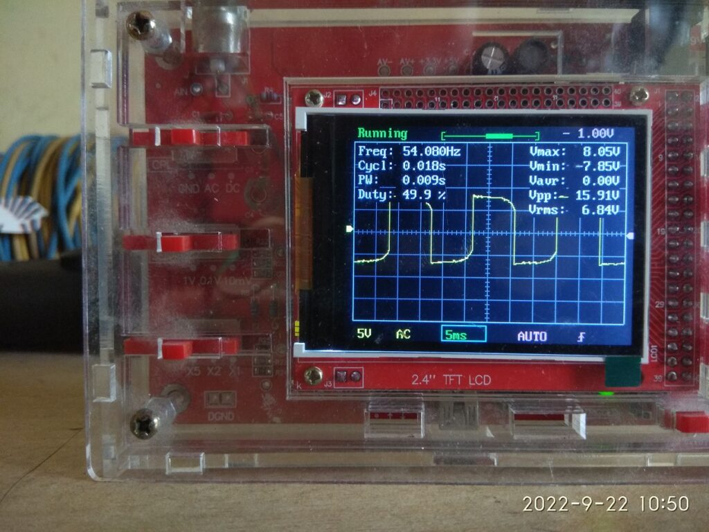
When the DC power was applied to the inverter and VFD was connected to the transformer output, but not yet switched on, the output from transformer showed as in below picture. Oscilloscope showing 8V means the AC output was +220/-220 V peak to peak and 6.84 x 27.5 = 188 VAC RMS. The DC voltage at inverter input was seen to be in range of 12V.
In this case, the LED display of VFD showed a DC input voltage as 172 VDC. This is not really adequate for a single phase solar VFD, while it requires 290 to 360VDC input for normal operation.
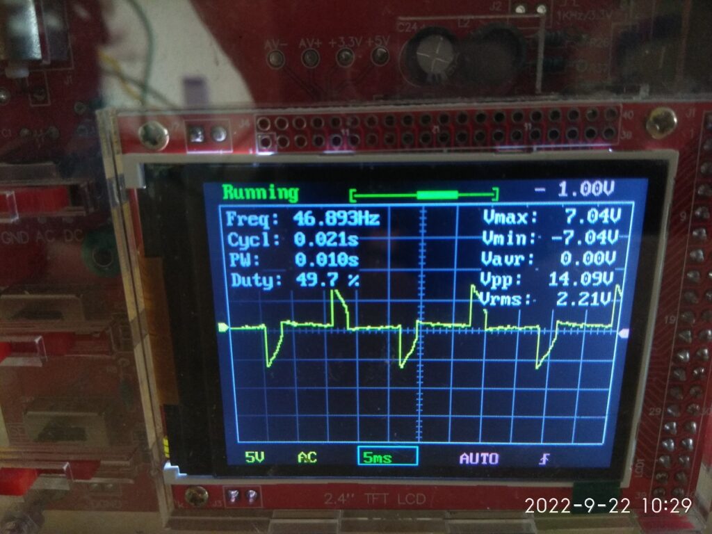
When VFD was switched on, the output voltage from transformer was seen to be reduced. Oscilloscope showing 7.04V means the AC output was +193/-193 V peak to peak, and 2.21 x 27.5 = 61 VAC rms. The DC voltage at inverter input was at 6V. More importantly the waveform is highly distorted and is most likely due to not enough driving power for the transfomer of the inverter, suggestive of shortfall in power available from solar panels.
It would be fair to conclude that this conept as such is ok but the voltage levels and power efficiency need to be experimented further and evaluated.
Adequate power and volage from Solar panels need to be made available on a bright sunny day.
May be, high frequency switching with suitable ferrite or equivalent transformer need to be used.
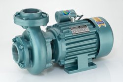
TBD.Centrifugal pumps running on normal AC power supply are very common, fairly efficient and most importantly they are locally available from wide range of manufacturers. Their use and operation is more or less hasslefree, they are easily serviceable at nearby workshops and pricewise also they are affordable. These points are specifically important in comparison to a classical solar pump system that is available in market these days, and which potentially uses a BLDC 3 phase DC motor/pump with permanent magnets and all stainless steel body.
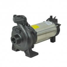
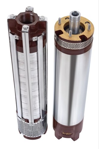
TBD.These standard AC pumps are available in 0.5 HP to 10s of HP of power rating, able to run on single phase (220V) or three phase (415V) AC power supply and available in formats like monoblock pumpset, openwell submersible and borewell submersible pumps.
TBD.Monoblock PumpTBD.Openwell Submersible PumpTBD.Borewell Submersible Pump, motor and pump shown separated from each other.
TBD.This article discusses the use of such standard AC pumps using Solar Panels as the source of electricity.
TBD.Since solar panels generate TBD.DC voltageTBD., it is important to have TBD.some mechanism or deviceTBD. to TBD.convert the DC electricity from the panels to AC powerTBD. so that the pump can run on it.
TBD.A standard AC motor consumes large amounts of current during startup for a few seconds, this current can be 2 to 6 times of the normal operating current at full load. On the other hand solar panels are a TBD.current limited source of powerTBD. i.e. the current output available from a given solar panel is limited by the size of panel. This means that the solar panels which would be sized and selected to meet the current requirements of the pump at normal operating load are not going to be able to start the pump in normal or traditional manner. TBD.Some kind of soft start approach is neededTBD..
TBD.Also based on sunlight available over the day time, the output voltage, current and power from solar panels is going to vary, this needs to be maximized by making the pump run at various voltage and/or AC frequency. The standard AC motor which is expected to operate at 50 Hz power supply, can actually be made to run over a range of supply frequency (35 to 55 Hz) without any significant side effects. In this range of frequency, the output power of the motor varies almost linearly and this inherent feature can be used to match the solar panel output with the pump-motor power requirements.
TBD.All the above leads to a solution which has to be based on some sort of electronics to support following features.
TBD.DC to AC conversion
TBD.Soft start or gradually increasing voltage during startup
TBD.Output voltage and frequency modulation to optimize the power generation from the solar panels.
TBD.For 1 and 2 above there already exists a robust industrial device called TBD.Variable Frequency Drive (VFD)TBD.. VFDs are often used in various industries to control the load and/or speed of standard AC motors which drive the heavy plant and machinery.
TBD.Most VFDs allow AC (single or three phase) or DC power supply as input and generate three phase AC power as output.
TBD.VFD – Variable Frequency Drive
TBD.Internally the input AC power supply is first rectified to DC, that is what makes VFD suitable to run with Solar Panels. Then a microcontroller based circuitry drives a set of power transistors (IGBT or MOSFETs) to achieve DC to AC conversion with a SPWM (sinusoidal pulse width modulation) technique.
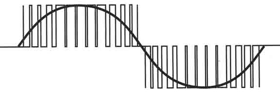
TBD.The output power is a sine wave with a configurable mains frequency (10 to 60 Hz as an example) but laden with spikes or chopped waveform with a carrier frequency of a few kilo-Hz. This is acceptable for standard AC motors, or rather the carrier frequency used in commercially available VFDs is optimized to keep the motors healthy and not to generate any ill-effects, especially high frequency harmonics.
TBD.Output Wavefrom from a VFD
TBD.The same waveform as explained and shown above, is generated in all the three phases of the output, but appropriately phase shifted by 120 degrees from each other. That makes a nice power source for a three phase AC motor.
TBD.During startup the VFD outputs a lower frequency of say 10 Hz and correspondingly lower pulse width (effectively a reduced AC voltage at the output). It is then gradually increased over a period of 5 to 15 seconds to normal operating frequency of 50 Hz. That is how a soft start is implemented.
TBD.VFDs have a simple and basic keypad with start, stop, menu buttons. Keypad permits setting of various configurable parameters, and also displays the operating status/errors if any.
TBD.Connectivity with external controlls is also provided, which allows dynamically setting the output frequency and voltage, external start and stop commands etc.
TBD.A fewer brands of VFDs have started manufacturing VFDs with additional features as below.
TBD.Customized phaseshift of 90/110 degrees (instead of 120) between the three output phases, to emulate the 3 wire power supply of a single phase capacitor run motor.
TBD.Changes to output frequency at runtime based on an inbuilt MPPT (maximum power point tracking) algorithm, essential for solar panels.
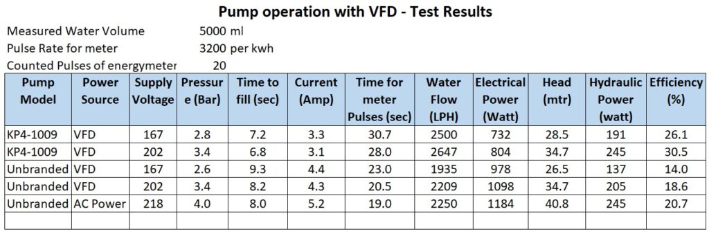
TBD.Test Results
TBD.With the concept explained so far as above, we have carried out a few real life tests using a VFD and borewell submersible pump.
TBD.Equipment used is listed below
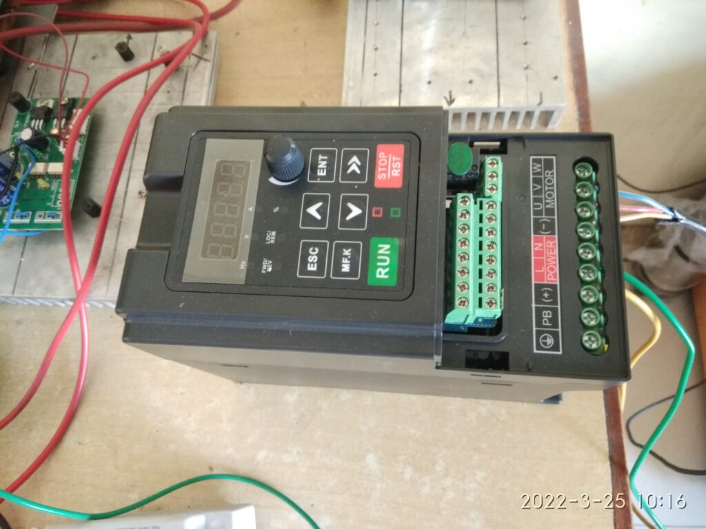
TBD.FRECON Make Solar VFD, model number FR150T – 2S – 2.2B -H, this accepts single phase AC input or DC input and gives out 3 phase 220 VAC. Has configuration settings to connect a single phase motor across the three U V W output terminals, and also has a MPPT algorithm in-built into it. It is not a Make In India brand but has ample presence of local dealer network in India. Build wise seems a good robust build.
TBD.Kirloskar make borewell submersible pump model Jalaraj KP4-1009 with 10 stages impeller, single phase 1 HP, 220VAC oil filled motor.
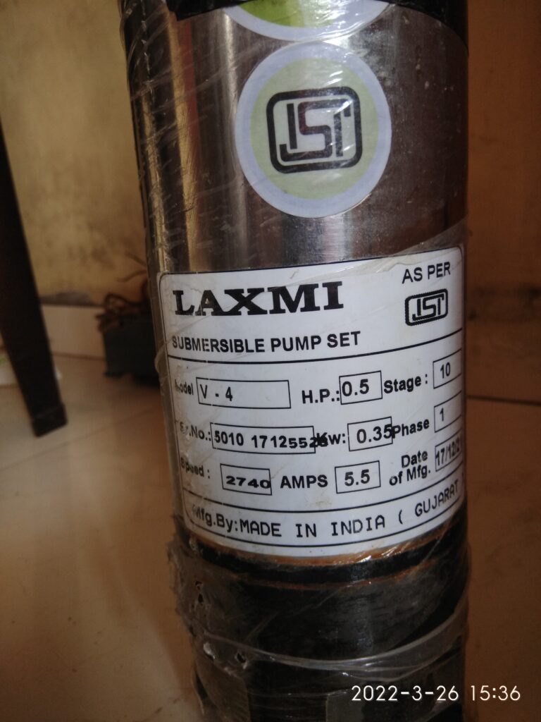
TBD.An unbranded borewell submersible pump, 10 stages, 0.5 HP 220VAC water filled motor, purchased from local market.
TBD.Energy Meter Secure Make, single phase 220VAC 30 Amps, 3200 pulses for 1 KWH unit consumption.
TBD.Power was taken from normal household AC supply
TBD.Water flow and pressure measurement was carried out using conventional simple techniques.
TBD.Normal AC power supply was connected to the input of VFD
TBD.Output terminals of the VFD were connected to the pump as given in the user guide of the VFD, i.e. TBD.UTBD.>>TBD.YTBD., TBD.VTBD.>>TBD.RTBD., TBD.WTBD.>>TBD.B
TBD.Two different voltage settings were used for testing at 100% and 80% of normal using F00.16 configuration of VFD.
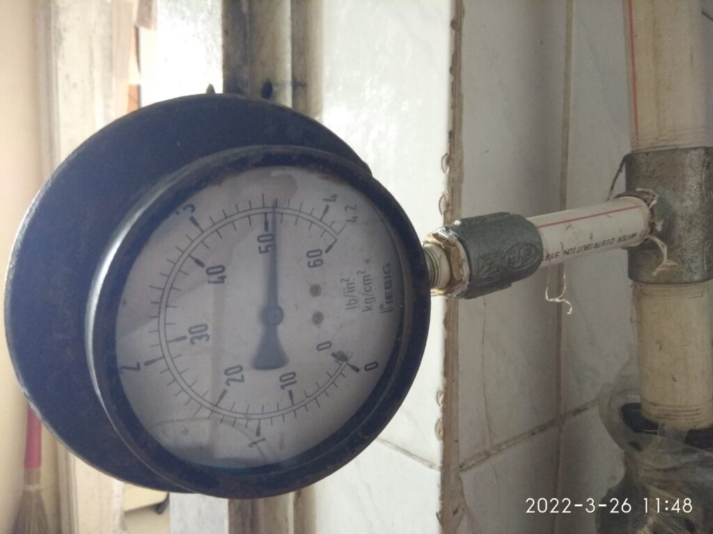
TBD.Valve in the delivery line was kept open in such a way as to be near the operating point to get 2.5 to 3.5 bar pressure and around 1800 LPH flow.
TBD.Below are few images and videos related to the tests carried out.
TBD.Short Video of the Trial Run, shows the simple setup, pump, energymeter and VFDTBD.Frecon VFDTBD.connection diagramTBD.Pressure GaugeTBD.Unbranded 0.5 HP pump, This turned out to be actually a 1 HP pump with much less efficiency than the Kirloskar PumpTBD.Output from VFD visually seen using light bulbs. VFD was configured for a single Phase Motor. This is typical to the FRECON Solar VFD model that they have provided a configuration setting. F08.00 = 2
TBD.Important observations
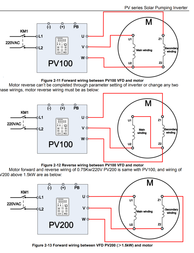
TBD.The VFD was tried in two different wiring arrangements. TBD.Two wire output modeTBD.: This is as per connection F08.00 = 1, whereby the run capacitor of the motor would be kept in circuit and only two wires of the VFD output were connected to the motor starter. In this case it was seen that the motor draws relatively more current untill it starts rotating and there after settles down to normal operating current. The starting current in this case is not as high as it would be otherwise on normal AC power supply, but still higher than running current. This is expected to be so and likely due to the inadequate capacitance at lower starting frequency. TBD.Three wire output mode:TBD. This is as per connection F08.00 = 2, as shown in figure 2.11 In this case the motor draws steadily and gradually increasing current until it stabilizes to the normal running current. TBD.This is a very important and useful aspect of the connection arrangement supported by this VFD since it will help deployment of optimum capacity of solar panels.
TBD.Further Work
TBD.It is essential to carry out similar tests with input power taken from suitably selected solar panels at various time of the day.
TBD.An online calculator for panel capacity is presented here at the below link. This will be useful to select the panel ratings for a given pump capacity.
TBD.On 30-March-2022 this VFD and 1HP single phase pump was installed at a farm site in Murbad.
TBD.Total of 1600 Watt Solar Panels are used to drive the VFD which is a mixed set as below. TBD.8 x 100 Watt 18 V in series with TBD. ( TBD. ( 4 x 100 Watt 46 V in series ) TBD. x 2 such strings in parallel TBD. )
TBD.It was seen that pump delivers 3000 to 3600 LPH water at about 30 feet total head, panel side voltage found to be in the order of 300 to 330 VDC, the VFD appropriately keeps regulating the output frequency from 35 to 50 Hz in order to maximize the solar energy generation from the panels and the VFD output voltage was seen to be in range of 160 to 220 VAC.
TBD.Long term trial run is planned and results will be published.
TBD.Video of the VFD in operation and solar panels used.TBD.Water flow from the pump
TBD.Centrifugal pumps running on normal AC power supply are very common, fairly efficient and most importantly they are locally available from wide range of manufacturers. Their use and operation is more or less hasslefree, they are easily serviceable at nearby workshops and pricewise also they are affordable. These points are specifically important in comparison to a classical solar pump system that is available in market these days, and which potentially uses a BLDC 3 phase DC motor/pump with permanent magnets and all stainless steel body.
TBD.These standard AC pumps are available in 0.5 HP to 10s of HP of power rating, able to run on single phase (220V) or three phase (415V) AC power supply and available in formats like monoblock pumpset, openwell submersible and borewell submersible pumps.
TBD.Monoblock PumpTBD.Openwell Submersible PumpTBD.Borewell Submersible Pump, motor and pump shown separated from each other.
TBD.This article discusses the use of such standard AC pumps using Solar Panels as the source of electricity.
TBD.Since solar panels generate TBD.DC voltageTBD., it is important to have TBD.some mechanism or deviceTBD. to TBD.convert the DC electricity from the panels to AC powerTBD. so that the pump can run on it.
TBD.A standard AC motor consumes large amounts of current during startup for a few seconds, this current can be 2 to 6 times of the normal operating current at full load. On the other hand solar panels are a TBD.current limited source of powerTBD. i.e. the current output available from a given solar panel is limited by the size of panel. This means that the solar panels which would be sized and selected to meet the current requirements of the pump at normal operating load are not going to be able to start the pump in normal or traditional manner. TBD.Some kind of soft start approach is neededTBD..
TBD.Also based on sunlight available over the day time, the output voltage, current and power from solar panels is going to vary, this needs to be maximized by making the pump run at various voltage and/or AC frequency. The standard AC motor which is expected to operate at 50 Hz power supply, can actually be made to run over a range of supply frequency (35 to 55 Hz) without any significant side effects. In this range of frequency, the output power of the motor varies almost linearly and this inherent feature can be used to match the solar panel output with the pump-motor power requirements.
TBD.All the above leads to a solution which has to be based on some sort of electronics to support following features.
TBD.DC to AC conversion
TBD.Soft start or gradually increasing voltage during startup
TBD.Output voltage and frequency modulation to optimize the power generation from the solar panels.
TBD.For 1 and 2 above there already exists a robust industrial device called TBD.Variable Frequency Drive (VFD)TBD.. VFDs are often used in various industries to control the load and/or speed of standard AC motors which drive the heavy plant and machinery.
TBD.Most VFDs allow AC (single or three phase) or DC power supply as input and generate three phase AC power as output.
TBD.VFD – Variable Frequency Drive
TBD.Internally the input AC power supply is first rectified to DC, that is what makes VFD suitable to run with Solar Panels. Then a microcontroller based circuitry drives a set of power transistors (IGBT or MOSFETs) to achieve DC to AC conversion with a SPWM (sinusoidal pulse width modulation) technique.
TBD.The output power is a sine wave with a configurable mains frequency (10 to 60 Hz as an example) but laden with spikes or chopped waveform with a carrier frequency of a few kilo-Hz. This is acceptable for standard AC motors, or rather the carrier frequency used in commercially available VFDs is optimized to keep the motors healthy and not to generate any ill-effects, especially high frequency harmonics.
TBD.Output Wavefrom from a VFD
TBD.The same waveform as explained and shown above, is generated in all the three phases of the output, but appropriately phase shifted by 120 degrees from each other. That makes a nice power source for a three phase AC motor.
TBD.During startup the VFD outputs a lower frequency of say 10 Hz and correspondingly lower pulse width (effectively a reduced AC voltage at the output). It is then gradually increased over a period of 5 to 15 seconds to normal operating frequency of 50 Hz. That is how a soft start is implemented.
TBD.VFDs have a simple and basic keypad with start, stop, menu buttons. Keypad permits setting of various configurable parameters, and also displays the operating status/errors if any.
TBD.Connectivity with external controlls is also provided, which allows dynamically setting the output frequency and voltage, external start and stop commands etc.
TBD.A fewer brands of VFDs have started manufacturing VFDs with additional features as below.
TBD.Customized phaseshift of 90/110 degrees (instead of 120) between the three output phases, to emulate the 3 wire power supply of a single phase capacitor run motor.
TBD.Changes to output frequency at runtime based on an inbuilt MPPT (maximum power point tracking) algorithm, essential for solar panels.
TBD.Test Results
TBD.With the concept explained so far as above, we have carried out a few real life tests using a VFD and borewell submersible pump.
TBD.Equipment used is listed below
TBD.FRECON Make Solar VFD, model number FR150T – 2S – 2.2B -H, this accepts single phase AC input or DC input and gives out 3 phase 220 VAC. Has configuration settings to connect a single phase motor across the three U V W output terminals, and also has a MPPT algorithm in-built into it. It is not a Make In India brand but has ample presence of local dealer network in India. Build wise seems a good robust build.
TBD.Kirloskar make borewell submersible pump model Jalaraj KP4-1009 with 10 stages impeller, single phase 1 HP, 220VAC oil filled motor.
TBD.An unbranded borewell submersible pump, 10 stages, 0.5 HP 220VAC water filled motor, purchased from local market.
TBD.Energy Meter Secure Make, single phase 220VAC 30 Amps, 3200 pulses for 1 KWH unit consumption.
TBD.Power was taken from normal household AC supply
TBD.Water flow and pressure measurement was carried out using conventional simple techniques.
TBD.Normal AC power supply was connected to the input of VFD
TBD.Output terminals of the VFD were connected to the pump as given in the user guide of the VFD, i.e. TBD.UTBD.>>TBD.YTBD., TBD.VTBD.>>TBD.RTBD., TBD.WTBD.>>TBD.B
TBD.Two different voltage settings were used for testing at 100% and 80% of normal using F00.16 configuration of VFD.
TBD.Valve in the delivery line was kept open in such a way as to be near the operating point to get 2.5 to 3.5 bar pressure and around 1800 LPH flow.
TBD.Below are few images and videos related to the tests carried out.
TBD.Short Video of the Trial Run, shows the simple setup, pump, energymeter and VFDTBD.Frecon VFDTBD.connection diagramTBD.Pressure GaugeTBD.Unbranded 0.5 HP pump, This turned out to be actually a 1 HP pump with much less efficiency than the Kirloskar PumpTBD.Output from VFD visually seen using light bulbs. VFD was configured for a single Phase Motor. This is typical to the FRECON Solar VFD model that they have provided a configuration setting. F08.00 = 2
TBD.Important observations
TBD.The VFD was tried in two different wiring arrangements. TBD.Two wire output modeTBD.: This is as per connection F08.00 = 1, whereby the run capacitor of the motor would be kept in circuit and only two wires of the VFD output were connected to the motor starter. In this case it was seen that the motor draws relatively more current untill it starts rotating and there after settles down to normal operating current. The starting current in this case is not as high as it would be otherwise on normal AC power supply, but still higher than running current. This is expected to be so and likely due to the inadequate capacitance at lower starting frequency. TBD.Three wire output mode:TBD. This is as per connection F08.00 = 2, as shown in figure 2.11 In this case the motor draws steadily and gradually increasing current until it stabilizes to the normal running current. TBD.This is a very important and useful aspect of the connection arrangement supported by this VFD since it will help deployment of optimum capacity of solar panels.
TBD.Further Work
TBD.It is essential to carry out similar tests with input power taken from suitably selected solar panels at various time of the day.
TBD.An online calculator for panel capacity is presented here at the below link. This will be useful to select the panel ratings for a given pump capacity.
TBD.On 30-March-2022 this VFD and 1HP single phase pump was installed at a farm site in Murbad.
TBD.Total of 1600 Watt Solar Panels are used to drive the VFD which is a mixed set as below. TBD.8 x 100 Watt 18 V in series with TBD. ( TBD. ( 4 x 100 Watt 46 V in series ) TBD. x 2 such strings in parallel TBD. )
TBD.It was seen that pump delivers 3000 to 3600 LPH water at about 30 feet total head, panel side voltage found to be in the order of 300 to 330 VDC, the VFD appropriately keeps regulating the output frequency from 35 to 50 Hz in order to maximize the solar energy generation from the panels and the VFD output voltage was seen to be in range of 160 to 220 VAC.
TBD.Long term trial run is planned and results will be published.
TBD.Video of the VFD in operation and solar panels used.TBD.Water flow from the pump
छोटे खेतों की सिंचाई के लिए जहां पानी का स्रोत पास में उपलब्ध है (या तो एक खुला कुआं, तालाब, झील या ऐसा कोई जल निकाय) छोटे पंपों का उपयोग करना और उन्हें सौर पैनलों पर संचालित करना संभव है।
ये पंप अधिकांश शहरों और छोटे शहरों में ऑनलाइन और साथ ही स्थानीय बाजार में उचित मूल्य पर आसानी से उपलब्ध हैं। वे आमतौर पर कीटनाशकों के लिए उपयोग किए जाने वाले बैटरी चालित बैकपैक स्प्रेयर में उपयोग किए जाते हैं।
This post explains some important aspects of this type of pumps for use at small irrigation sites.
यह पोस्ट छोटे सिंचाई स्थलों पर उपयोग के लिए इस प्रकार के पंपों के कुछ महत्वपूर्ण पहलुओं की व्याख्या करता है।
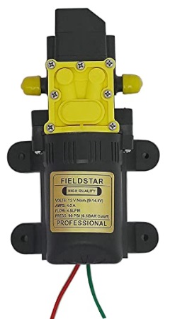
Such a pump is run by a DC motor and has a PVC block head where positive displacement of water is achieved by action of miniaturized pistons inside the block.
ऐसा पंप डीसी मोटर द्वारा चलाया जाता है और इसमें पीवीसी ब्लॉक हेड होता है जहां ब्लॉक के अंदर छोटे पिस्टन की क्रिया द्वारा पानी का दबाव बढाया जाता है।
A pump having single motor is often priced at 550 to 650 INR and delivers upto 3 LPM water and claims to generate pressure of 70 PSI or 5 Bar i.e. upto 50 meters of height.
सिंगल मोटर वाले एक पंप की कीमत अक्सर 550 से 650 रुपये होती है और यह 3 लिटर प्रति मिनिट तक पानी दे सकता है और 70 पीएसआई या 5 बार यानी 50 मीटर ऊंचाई तक का दबाव उत्पन्न करने का दावा करता है।
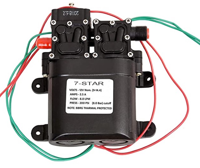
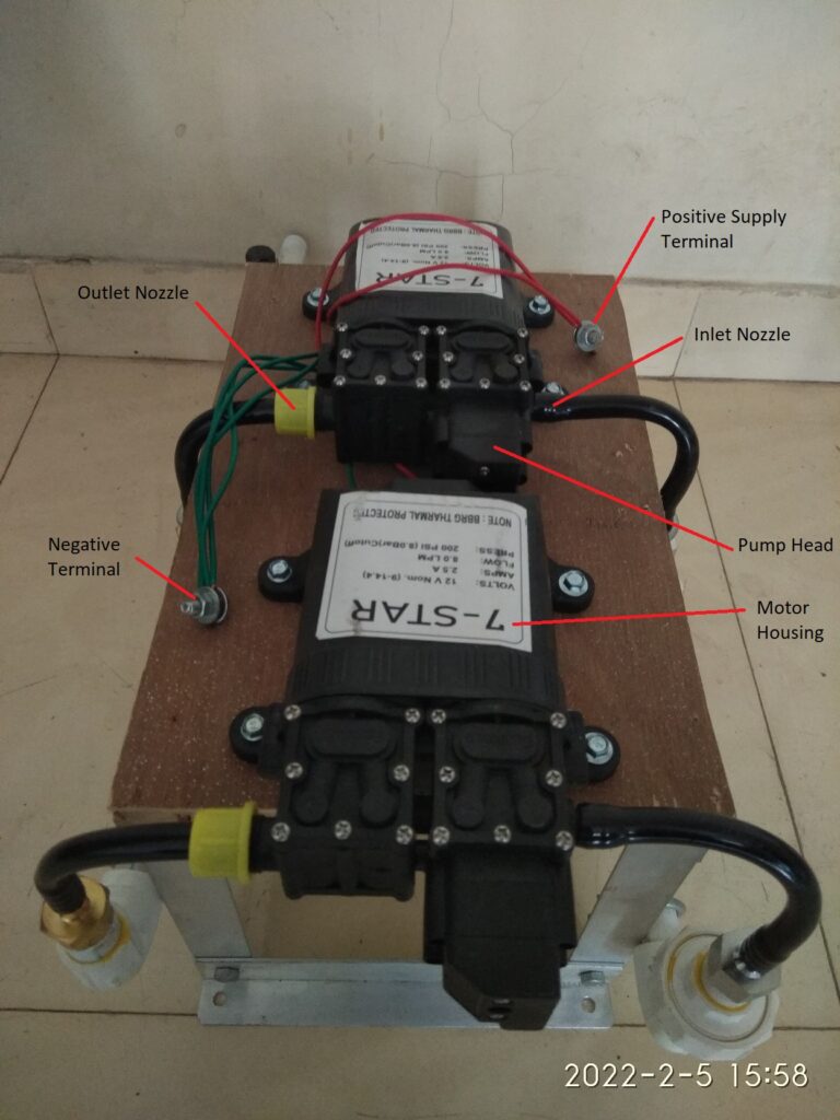
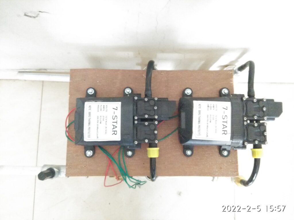
Pump with twin motor is also available and priced at 1000 INR, delivers 5 to 6 LPM of water at similar pressure.
दो मोटर वाला पंप भी उपलब्ध है और इसकी कीमत लगभग 1000 रुपये है, समान दबाव पर 5 से 6 लीटर पानी की आपूर्ति करता है।
Next two images show a single motor and dual or twin motor pump.
अगली दो छवियां एकल मोटर और दोहरी या जुड़वां मोटर पंप दिखाती हैं।
The DC Motor used is a DC motor with brushes and follows a standard specification named as 775 motor, some details can be found here.
The motor can be operated over a wide range of DC supply voltage (6 to 36VDC) but the pump manufacturers normally mark the pump for operation in range of 12 to 14.5 VDC only.
We have installed such pumps at a couple of sites and safely connected to solar panels of 12VDC nominal (or 18VDC MPPT voltage). The motor of the pump nicely works with the electricity generated by solar panel during the daytime. As the intensity of sunlight changes throughout the day, the output flow of water varies and is acceptable for the irrigation purposes.
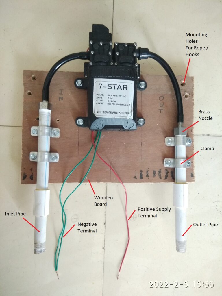
Inlet and outlet of the pump is however a non-standard (or at least not easily available) tubing size. Most suppliers provide a PVC/HDPE tube with threaded PVC nut to attach to the pump outlet nozzle, but the connectors with standard pipe sizes (say 0.5 or 1 inch nominal bore pipe) are difficult to find.
We have used a typical nozzle connection seen in pictures and created a simple skid mounted assembly of this type of pumps, eiether one pump on the skid or 2 on the skid as per the requirements.
With 2 pumps on the skid it is seen that 150 to 200 watt panels are adequate for operation throughout the day. For single pump a panel of 75 to 100 watt is appropriate.
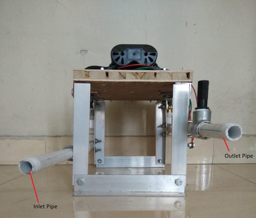
Next few images explain the mounting approach we have used and is only a suggestion. Any suitable alternative can be followed that meets the needs and materials availability at the installation site.
Single Pump Skid
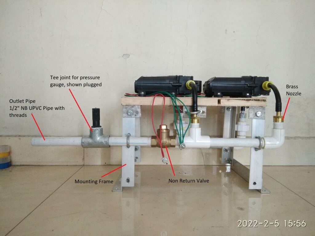
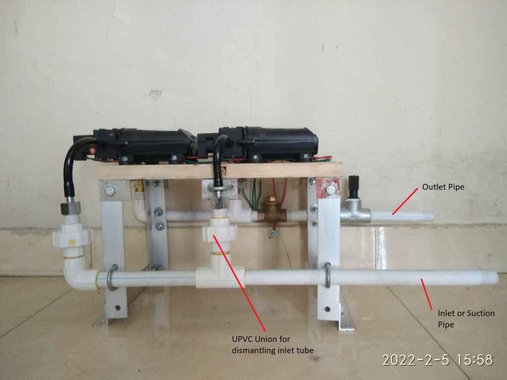
Dual Pump Skid
Front view of the pump skid with inlet and outlet pipes on left side.
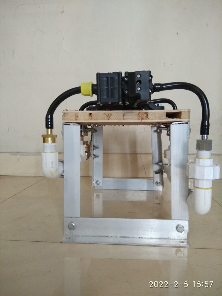
Seen from top at an angle / 3-D view.
Left Side View
Rear View
Right Side View
Top View
Important Instructions
Pump and motor must never be submerged in water and water must not get into the motor.
DC power supply polarity needs to be correctly followed. Green wires to be connected to negative terminal of the battery or solar panels, and red wire to positive terminal.
DC supply voltage must never exceed 18 volts.
In no case, AC supply / mains supply shall be applied to the motor, it is hazardous besides the fact that it will permanently damage the motor.
Testing of pump without water by supplying DC power for a second or say two seconds is ok, but must not run the motor for longer duration without water.
At the inlet pipe a suitable filter in form of nylon mesh is highly recommended. The internal piston mechanism of the pump is too small to get clogged by smallest of the particles.
This type of pump can generally start from dry run and can self prime in a few seconds, but if it does not do so, please do not run it dry for long time. Instead open the nozzles and check if any clogging or blockages. Try to pull water from outlet nozzle or pipe by sucking the air.
The pump can lift water from upto 5-6 feet on the suction side, however it is better to keep the suction pipe length as small as possible.
It is recommended to install a footvalve at end of the suction pipe submerged inside the water, it is best to attach a filter mesh around the footvalve.
Make sure that the pump skid is mounted on a sturdy platform or base. Alternatively pump can be suspeneded firmly inside an openwell clearly above the water level.
Use solar panels of 12VDC nominal voltage only, any higher voltage panels if connected to the pump will damage the same. It is better to first check the nameplate on the backside of the solar panel before connecting for the first time. The nameplate should read 12VDC nominal and/or 17-18 VDC MPPT or maximum power voltage.
Single pump skid is suitable to operate with 75 to 100 Watt panel and dual pump skid with 150 to 200 Watts. Excessively higher wattage of the solar panels must be avoided.
This type of pump is supposed to be used for intermittent duty only however through our experimentation in actual sites, we find that using the pump every day for 3 to 5 hours is fine.
Connect the outlet pipe with suitable coupling or union with the delivery pipe to be arranged at the site to suit the distance of the final delivery location away from the water source.
Ensure that the inlet and outlet pipe connections do not lead to forces on the pipes or the skid.
If in doubt please reach out to us through email or phone.
Centrifugal pumps running on normal AC power supply are very common, fairly efficient and most importantly they are locally available from wide range of manufacturers. Their use and operation is more or less hasslefree, they are easily serviceable at nearby workshops and pricewise also they are affordable. These points are specifically important in comparison to a classical solar pump system that is available in market these days, and which potentially uses a BLDC 3 phase DC motor/pump with permanent magnets and all stainless steel body.
These standard AC pumps are available in 0.5 HP to 10s of HP of power rating, able to run on single phase (220V) or three phase (415V) AC power supply and available in formats like monoblock pumpset, openwell submersible and borewell submersible pumps.
Monoblock PumpOpenwell Submersible PumpBorewell Submersible Pump, motor and pump shown separated from each other.
This article discusses the use of such standard AC pumps using Solar Panels as the source of electricity.
Since solar panels generate DC voltage, it is important to have some mechanism or device to convert the DC electricity from the panels to AC power so that the pump can run on it.
A standard AC motor consumes large amounts of current during startup for a few seconds, this current can be 2 to 6 times of the normal operating current at full load. On the other hand solar panels are a current limited source of power i.e. the current output available from a given solar panel is limited by the size of panel. This means that the solar panels which would be sized and selected to meet the current requirements of the pump at normal operating load are not going to be able to start the pump in normal or traditional manner. Some kind of soft start approach is needed.
Also based on sunlight available over the day time, the output voltage, current and power from solar panels is going to vary, this needs to be maximized by making the pump run at various voltage and/or AC frequency. The standard AC motor which is expected to operate at 50 Hz power supply, can actually be made to run over a range of supply frequency (35 to 55 Hz) without any significant side effects. In this range of frequency, the output power of the motor varies almost linearly and this inherent feature can be used to match the solar panel output with the pump-motor power requirements.
All the above leads to a solution which has to be based on some sort of electronics to support following features.
DC to AC conversion
Soft start or gradually increasing voltage during startup
Output voltage and frequency modulation to optimize the power generation from the solar panels.
For 1 and 2 above there already exists a robust industrial device called Variable Frequency Drive (VFD). VFDs are often used in various industries to control the load and/or speed of standard AC motors which drive the heavy plant and machinery.
Most VFDs allow AC (single or three phase) or DC power supply as input and generate three phase AC power as output.
VFD – Variable Frequency Drive
Internally the input AC power supply is first rectified to DC, that is what makes VFD suitable to run with Solar Panels. Then a microcontroller based circuitry drives a set of power transistors (IGBT or MOSFETs) to achieve DC to AC conversion with a SPWM (sinusoidal pulse width modulation) technique.
The output power is a sine wave with a configurable mains frequency (10 to 60 Hz as an example) but laden with spikes or chopped waveform with a carrier frequency of a few kilo-Hz. This is acceptable for standard AC motors, or rather the carrier frequency used in commercially available VFDs is optimized to keep the motors healthy and not to generate any ill-effects, especially high frequency harmonics.
Output Wavefrom from a VFD
The same waveform as explained and shown above, is generated in all the three phases of the output, but appropriately phase shifted by 120 degrees from each other. That makes a nice power source for a three phase AC motor.
During startup the VFD outputs a lower frequency of say 10 Hz and correspondingly lower pulse width (effectively a reduced AC voltage at the output). It is then gradually increased over a period of 5 to 15 seconds to normal operating frequency of 50 Hz. That is how a soft start is implemented.
VFDs have a simple and basic keypad with start, stop, menu buttons. Keypad permits setting of various configurable parameters, and also displays the operating status/errors if any.
Connectivity with external controlls is also provided, which allows dynamically setting the output frequency and voltage, external start and stop commands etc.
A fewer brands of VFDs have started manufacturing VFDs with additional features as below.
Customized phaseshift of 90/110 degrees (instead of 120) between the three output phases, to emulate the 3 wire power supply of a single phase capacitor run motor.
Changes to output frequency at runtime based on an inbuilt MPPT (maximum power point tracking) algorithm, essential for solar panels.
Test Results
With the concept explained so far as above, we have carried out a few real life tests using a VFD and borewell submersible pump.
Equipment used is listed below
FRECON Make Solar VFD, model number FR150T – 2S – 2.2B -H, this accepts single phase AC input or DC input and gives out 3 phase 220 VAC. Has configuration settings to connect a single phase motor across the three U V W output terminals, and also has a MPPT algorithm in-built into it. It is not a Make In India brand but has ample presence of local dealer network in India. Build wise seems a good robust build.
Kirloskar make borewell submersible pump model Jalaraj KP4-1009 with 10 stages impeller, single phase 1 HP, 220VAC oil filled motor.
An unbranded borewell submersible pump, 10 stages, 0.5 HP 220VAC water filled motor, purchased from local market.
Energy Meter Secure Make, single phase 220VAC 30 Amps, 3200 pulses for 1 KWH unit consumption.
Power was taken from normal household AC supply
Water flow and pressure measurement was carried out using conventional simple techniques.
Normal AC power supply was connected to the input of VFD
Output terminals of the VFD were connected to the pump as given in the user guide of the VFD, i.e. U>>Y, V>>R, W>>B
Two different voltage settings were used for testing at 100% and 80% of normal using F00.16 configuration of VFD.
Valve in the delivery line was kept open in such a way as to be near the operating point to get 2.5 to 3.5 bar pressure and around 1800 LPH flow.
Below are few images and videos related to the tests carried out.
Short Video of the Trial Run, shows the simple setup, pump, energymeter and VFDFrecon VFDconnection diagramPressure GaugeUnbranded 0.5 HP pump, This turned out to be actually a 1 HP pump with much less efficiency than the Kirloskar PumpOutput from VFD visually seen using light bulbs. VFD was configured for a single Phase Motor. This is typical to the FRECON Solar VFD model that they have provided a configuration setting. F08.00 = 2
Important observations
The VFD was tried in two different wiring arrangements. Two wire output mode: This is as per connection F08.00 = 1, whereby the run capacitor of the motor would be kept in circuit and only two wires of the VFD output were connected to the motor starter. In this case it was seen that the motor draws relatively more current untill it starts rotating and there after settles down to normal operating current. The starting current in this case is not as high as it would be otherwise on normal AC power supply, but still higher than running current. This is expected to be so and likely due to the inadequate capacitance at lower starting frequency. Three wire output mode: This is as per connection F08.00 = 2, as shown in figure 2.11 In this case the motor draws steadily and gradually increasing current until it stabilizes to the normal running current. This is a very important and useful aspect of the connection arrangement supported by this VFD since it will help deployment of optimum capacity of solar panels.
Further Work
It is essential to carry out similar tests with input power taken from suitably selected solar panels at various time of the day.
An online calculator for panel capacity is presented here at the below link. This will be useful to select the panel ratings for a given pump capacity.
On 30-March-2022 this VFD and 1HP single phase pump was installed at a farm site in Murbad.
Total of 1600 Watt Solar Panels are used to drive the VFD which is a mixed set as below. 8 x 100 Watt 18 V in series with ( ( 4 x 100 Watt 46 V in series ) x 2 such strings in parallel )
It was seen that pump delivers 3000 to 3600 LPH water at about 30 feet total head, panel side voltage found to be in the order of 300 to 330 VDC, the VFD appropriately keeps regulating the output frequency from 35 to 50 Hz in order to maximize the solar energy generation from the panels and the VFD output voltage was seen to be in range of 160 to 220 VAC.
Long term trial run is planned and results will be published.
Video of the VFD in operation and solar panels used.Water flow from the pump
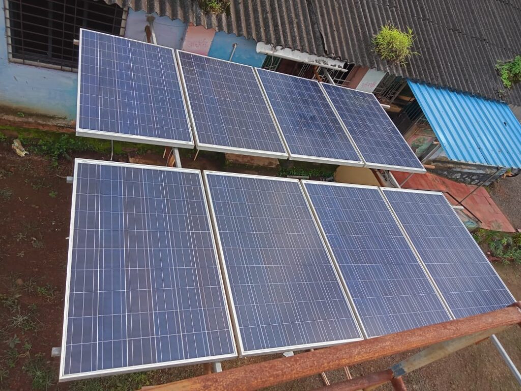
We see solar panels installed at various places but not in use due to various reasons like
Cables broken
Battery not existing or damaged / end of life
Devices powered from the panels no more existing or damaged beyond repairs.
Few from the set of panels are damaged / glass broken.
These panels are in various sizes starting from as small as 20 watt to 250 or 300 watt per panel and in numbers ranging from 1 to 8 or 12 at any one given site.
Such installations are a common sight in rural areas, in form of Grampanchayat Solar Street Lights, and at Z P Schools where a battery based solar electric system was previously installed. Such ZP school systems, as far as we have seen, are in range of 1 to 2 KW solar panels capacity and provided with fairly large size batteries.
Besides providing power in case of outage of electricity from MSEDCL, these solar systems were seemingly intended to supply daily electricity to the school and in turn reduce the consumption and to lead to lower or zero bill charges every month.
Present Situation
At the ZP schools where a battery based solar system has been installed, most often, after 2-3 years if not less, the useful life of the original supplied battery has expired and there are no arrangements to procure a new set of batteries.
In such cases the existing battery can not store the electricity generated by the panels and thus the school has to consume electricity from the grid through the energy meter provided by MSEDCL.
The connection provided to ZP schools by MSEDCL often is set to have a tariff category named LT Public Services Govt. Education. This tariff category has a monthly fixed charge (स्थिर आकार ) of 343 INR, which means that even if there is no energy consumption in a month, the school needs to pay this much amount towards electricity bill every month.
To summarize, such schools do have solar panels and dead batteries and on the other hand end up paying electricity bill every month.
Most schools need to pay bill from their funds whatever available or rely on Grampanchayat team to pay the bills. It is more often meticulous followup and related hassles of potentially untimely payments, sometimes leading to disconnection of electric supply to the school.
Proposal
We propose that such sites are best suited for using the existing panels in a net metering arrangement with MSEDCL for the school.
We have carried out a survey to know what is the most important concern of the school teachers when it comes to electric supply, and below are the findings from schools in Murbad taluka of Thane district.
Survey Results
Concern
Votes
महावितरणकडून तांत्रिक कामांमुळे/दोषामुळे काही कालावधीसाठी वीजपुरवठा खंडीत होणे – ह्यापासून मुक्तता आवश्यक
6
वीजबिल भरण्याची अनियमितता, कटकट, खिशाला कात्री, निधीची कमतरता, बिल ना भरल्यामुळे वीजपुरवठा खंडीत केला जाण्याची भिती – ह्यापासून मुक्तता आवश्यक
86
As can be seen the majority of survey participants have expressed an opinion that reduction in the monthly electric bills is more important.
Proposal Details
As a part of net metering arrangement, there is no need to install/maintain any batteries, electricity units generated from solar panels are used internally for school consumption and any excess are exported to electric grid.
The net metering approach involves following steps.
Permission for Solar Net Metering installation is to be formally obtained from MSEDCL for the consumer number of the school, through the online application form, application fees 590 INR need to be paid.
Existing solar panels are used to produce electricity.
If needed, the support structure for the panels may have to be reconstructed, approx cost 10000 INR.
DC electricity generated by panels is converted to AC power using a Solar Grid Tie Inverter, approx cost 23000 INR. The inverter is the only component that may need servicing in a very rare case, but comes with a 5 years warranty.
A Generation meter is installed which records the electricity units produced by the solar panels. Approx cost 1200 INR.
A Net meter is installed to measure the units Imported from and Exported to the MSEDCL grid, approx cost 2800 INR.
Net Meter is provided to MSEDCL for testing, fees 590 INR
Net Metering agreement as per standard content given by MSEDCL is prepared and printed on 200 INR stamp-paper to be handed over to MSEDCL.
MSEDCL, after site inspection, will hook up the net meter replacing the old meter.
Solar readings are then captured regularly by MSEDCL staff and billing as per the readings is initiated by MSEDCL as standard process.
As can be seen a total expenditure of about 45000 INR is necessary for a 2 KW system with existing panels to be put to use.
Benefits
Near 0 amount of monthly power bill and no more fear of power disconnection for school.
Utilization of an important asset which otherwise would have simply been a waste/idle, namely the solar panels.
Green energy initiative put to practice.
All of this for about 20+ years, thus saving money for the Grampanchayat.
Sample Installation
Starting in early 2021, and funded by Malati Vaidya Smruti Trust, a solar net metering installation has been successfully completed for consumer number 019000002570, Z.P. School, Milhe, Mhasa Dhasai Road, Murbad.
2 KW old panels were available from a not-in-use solar pump in custody of the Grampanchayat, who handed over the panels to school for the solar net metering project.
Just rececntly solar billing has started and school is seeing excess units exported to MSEDCL, these will be converted to monetary credit in the electricity bill for the school in month of March or April. Thereafter the credit amount will get utilized to pay off for the monthly fixed charges of subsequent months.
Request For Support
We seek contributors and donors to fund such projects and thus put to use the idling infrastructure (mainly the solar panels) and help the schools reduce their electric bills as much as possible.
For irrigation of small farms where water source is available nearby (either an open well, pond, lake or any such water-body) it is possible to use small pumps and operate them on solar panels.
छोटे खेतों की सिंचाई के लिए जहां पानी का स्रोत पास में उपलब्ध है (या तो एक खुला कुआं, तालाब, झील या ऐसा कोई जल निकाय) छोटे पंपों का उपयोग करना और उन्हें सौर पैनलों पर संचालित करना संभव है।
These pumps are easily available at reasonable prices online as well as in local market in most of the cities and small towns accessible to farmers. They are used very commonly in battery operated backpack sprayers used for pesticides.
ये पंप अधिकांश शहरों और छोटे शहरों में ऑनलाइन और साथ ही स्थानीय बाजार में उचित मूल्य पर आसानी से उपलब्ध हैं। वे आमतौर पर कीटनाशकों के लिए उपयोग किए जाने वाले बैटरी चालित बैकपैक स्प्रेयर में उपयोग किए जाते हैं।
This post explains some important aspects of this type of pumps for use at small irrigation sites.
यह पोस्ट छोटे सिंचाई स्थलों पर उपयोग के लिए इस प्रकार के पंपों के कुछ महत्वपूर्ण पहलुओं की व्याख्या करता है।
Such a pump is run by a DC motor and has a PVC block head where positive displacement of water is achieved by action of miniaturized pistons inside the block.
ऐसा पंप डीसी मोटर द्वारा चलाया जाता है और इसमें पीवीसी ब्लॉक हेड होता है जहां ब्लॉक के अंदर छोटे पिस्टन की क्रिया द्वारा पानी का दबाव बढाया जाता है।
A pump having single motor is often priced at 550 to 650 INR and delivers upto 3 LPM water and claims to generate pressure of 70 PSI or 5 Bar i.e. upto 50 meters of height.
सिंगल मोटर वाले एक पंप की कीमत अक्सर 550 से 650 रुपये होती है और यह 3 लिटर प्रति मिनिट तक पानी दे सकता है और 70 पीएसआई या 5 बार यानी 50 मीटर ऊंचाई तक का दबाव उत्पन्न करने का दावा करता है।
Pump with twin motor is also available and priced at 1000 INR, delivers 5 to 6 LPM of water at similar pressure.
दो मोटर वाला पंप भी उपलब्ध है और इसकी कीमत लगभग 1000 रुपये है, समान दबाव पर 5 से 6 लीटर पानी की आपूर्ति करता है।
Next two images show a single motor and dual or twin motor pump.
अगली दो छवियां एकल मोटर और दोहरी या जुड़वां मोटर पंप दिखाती हैं।
The DC Motor used is a DC motor with brushes and follows a standard specification named as 775 motor, some details can be found here.
The motor can be operated over a wide range of DC supply voltage (6 to 36VDC) but the pump manufacturers normally mark the pump for operation in range of 12 to 14.5 VDC only.
We have installed such pumps at a couple of sites and safely connected to solar panels of 12VDC nominal (or 18VDC MPPT voltage). The motor of the pump nicely works with the electricity generated by solar panel during the daytime. As the intensity of sunlight changes throughout the day, the output flow of water varies and is acceptable for the irrigation purposes.
Inlet and outlet of the pump is however a non-standard (or at least not easily available) tubing size. Most suppliers provide a PVC/HDPE tube with threaded PVC nut to attach to the pump outlet nozzle, but the connectors with standard pipe sizes (say 0.5 or 1 inch nominal bore pipe) are difficult to find.
We have used a typical nozzle connection seen in pictures and created a simple skid mounted assembly of this type of pumps, eiether one pump on the skid or 2 on the skid as per the requirements.
With 2 pumps on the skid it is seen that 150 to 200 watt panels are adequate for operation throughout the day. For single pump a panel of 75 to 100 watt is appropriate.
Next few images explain the mounting approach we have used and is only a suggestion. Any suitable alternative can be followed that meets the needs and materials availability at the installation site.
Single Pump Skid
Dual Pump Skid
Front view of the pump skid with inlet and outlet pipes on left side.
Seen from top at an angle / 3-D view.
Left Side View
Rear View
Right Side View
Top View
Important Instructions
Pump and motor must never be submerged in water and water must not get into the motor.
DC power supply polarity needs to be correctly followed. Green wires to be connected to negative terminal of the battery or solar panels, and red wire to positive terminal.
DC supply voltage must never exceed 18 volts.
In no case, AC supply / mains supply shall be applied to the motor, it is hazardous besides the fact that it will permanently damage the motor.
Testing of pump without water by supplying DC power for a second or say two seconds is ok, but must not run the motor for longer duration without water.
At the inlet pipe a suitable filter in form of nylon mesh is highly recommended. The internal piston mechanism of the pump is too small to get clogged by smallest of the particles.
This type of pump can generally start from dry run and can self prime in a few seconds, but if it does not do so, please do not run it dry for long time. Instead open the nozzles and check if any clogging or blockages. Try to pull water from outlet nozzle or pipe by sucking the air.
The pump can lift water from upto 5-6 feet on the suction side, however it is better to keep the suction pipe length as small as possible.
It is recommended to install a footvalve at end of the suction pipe submerged inside the water, it is best to attach a filter mesh around the footvalve.
Make sure that the pump skid is mounted on a sturdy platform or base. Alternatively pump can be suspeneded firmly inside an openwell clearly above the water level.
Use solar panels of 12VDC nominal voltage only, any higher voltage panels if connected to the pump will damage the same. It is better to first check the nameplate on the backside of the solar panel before connecting for the first time. The nameplate should read 12VDC nominal and/or 17-18 VDC MPPT or maximum power voltage.
Single pump skid is suitable to operate with 75 to 100 Watt panel and dual pump skid with 150 to 200 Watts. Excessively higher wattage of the solar panels must be avoided.
This type of pump is supposed to be used for intermittent duty only however through our experimentation in actual sites, we find that using the pump every day for 3 to 5 hours is fine.
Connect the outlet pipe with suitable coupling or union with the delivery pipe to be arranged at the site to suit the distance of the final delivery location away from the water source.
Ensure that the inlet and outlet pipe connections do not lead to forces on the pipes or the skid.
If in doubt please reach out to us through email or phone.
Demonstration of 3 pumps at a site in murbad
Update on 21-Sep-2022
We have taken measurements of the pressure and flow generated from this type of mini pump and the videos below are useful to understand the performance.
It was seen that when operating with a 16VDC power adapter one twin pump could produce 2 Bar pressure (20 mtr water column equivalent).
At 1.5 bar the pump delivered 180 LPH and at 1.0 bar the pump could deliver 300 LPH of water flow.
For our community projects executed by Malati Vaidya Smruti Trust and Water Group, we often need data collected from various locations like lat long and dimensions of an existing bandhara wall (weir) on a river, or sequencial path of lat long points from a borewell to a nearby school.
This data can be captured on smartphones which are commonly available with local people nowadays, using various apps like My Tracks. But most such apps need the internet / data connection to be always enabled / available on the phone. At most of the locations which are remote areas, mobile network and data connectivity are not available.
मालती वैद्य स्मृती ट्रस्ट आणि वॉटर ग्रुपद्वारे राबविल्या गेलेल्या आमच्या सामुदायिक प्रकल्पांसाठी आम्हाला अनेकदा वेगवेगळ्या ठिकाणांहून माहिती गोळा करावी लागते जसे की एखाद्या अस्तित्त्वात असलेल्या बंधाराच्या भिंतीच्या जागेवर जाऊन त्याची लांबी, रुंदी, अक्षांश आणि रेखांश नोंदी घेणे किंवा एखाद्या बोअरवेलपासून शाळेपर्यंतचा मार्ग आणि त्यावरील नोंद करावयाचे अक्षांश आणि रेखांश.
माय ट्रॅक्स सारख्या विविध अॅप्सचा वापर करून आजकाल स्थानिक लोकांकडे सहज उपलब्ध असणाऱ्या स्मार्टफोनमध्ये हा डेटा नोंद केला जाऊ शकतो. परंतु अश्या बर्याच अॅप्ससाठी फोनवर उपलब्ध असलेले इंटरनेट / डेटा कनेक्शन गरजेचे असते. दुर्गम भागातील बर्याच ठिकाणी, मोबाइल नेटवर्क आणि डेटा कनेक्टिव्हिटी उपलब्ध नसते .
This requires that there needs to be some offline data collection mechanism, which will also allow submitting the data to central data server/repository whenever the data connectivity is available.
या समस्येवर मात करण्यासाठी एखादी ऑफलाइन डेटा संकलन प्रणाली असणे आवश्यक आहे, ज्याद्वारे जेव्हा कधी डेटा कनेक्टिव्हिटी उपलब्ध असेल तेव्हा ऑफलाईन पद्धतीने नोंद केलेला डेटा सेंट्रल सर्व्हर/रेपॉजिटरीमध्ये पाठवता येऊ शकेल.
We find that, ODK collect – which is a free to use app, can be the most (if not the best) suited and user friendly option for this purpose.
थोडी शोधाशोध केल्यावर आम्हाला असे आढळले की, ओडीके कलेक्ट – जे वापरण्यासाठी विनामूल्य आहे, या कामी बरेचसे योग्य आणि वापरकर्त्यांच्या दृष्टीने अनुकूल पर्याय होऊ शकते.
Pre-requisitesfor the End User
साधारण वापरकर्त्यांसाठी पूर्वतयारी
End User is a person who will be given the task of capturing data using the forms created by admin user.
User should have an android based smartphone with mobile data or wifi connection that has to be operational from his home or one such place.
User needs to have created his Google email id and it needs to be active.
Google drive app installed on phone.
ODK Collect app installed and configured on phone.
साधारण वापरकर्ता ही अशी व्यक्ती आहे जी उपलब्ध फॉर्मचा वापर करुन माहिती संकलनाचे (डेटा कॅप्चर) काम करील.
वापरकर्त्याकडे मोबाइल डेटा किंवा वायफाय कनेक्शनसह Android आधारित स्मार्टफोन असावा. डेटा /वायफाय कनेक्शन त्याच्या घरातून किंवा किमान एका तरी ठिकाणी कार्यरत असणे गरजेचे आहे.
वापरकर्त्याने त्याचा Google ईमेल आयडी तयार करणे आवश्यक आहे आणि ई-मेल सक्रिय असणे आवश्यक आहे.
फोनवर Google ड्राइव्ह अॅप इन्स्टॉल केलेले पाहीजे
ओडीके कलेक्ट अॅप फोनवर स्थापित आणि सेट-अप केलेले पाहीजे.
Setting up ODK Collect App (All Users)
ODK कलेक्ट अॅप सेट अप करणे (सर्व वापरकर्ते – साधारण तसेच अॅडमिन वापरकर्ते )
These steps, as a part of Setting up ODK Collect app, require data connectivity enabled on your mobile phone.
On your smartphone go to Play Store, Search app by name ODK Collect, Download and install the app.
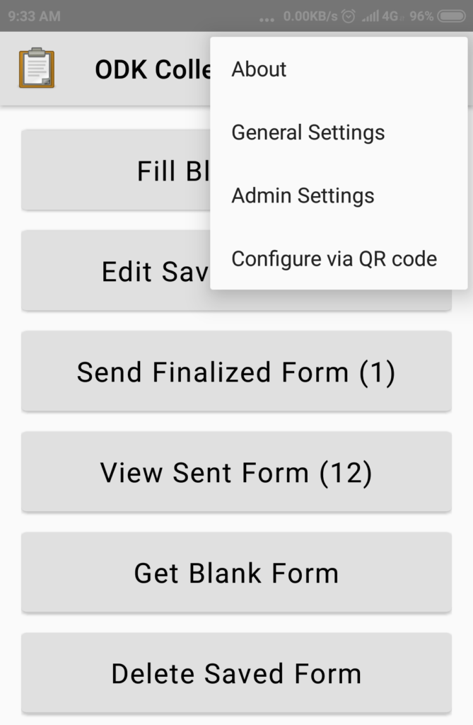
When the ODK Collect app is started it will show its home page as below.
ओडीके कलेक्ट अॅप सेट-अप करताना आपल्या मोबाइल फोनवर डेटा कनेक्टिव्हिटी सुरू केलेली असणे आवश्यक आहे. आपल्या स्मार्टफोनमध्ये प्ले स्टोअरवर जा, ओडीके कलेक्ट नावाचे अॅप शोधा, अॅप डाउनलोड करा आणि इन्स्टॉल करा. जेव्हा ओडीके कलेक्ट अॅप सुरू होईल तेव्हा खालील प्रमाणे मुख्य पृष्ठ दिसेल .
In right top corner menu of the app, you can see options as below.
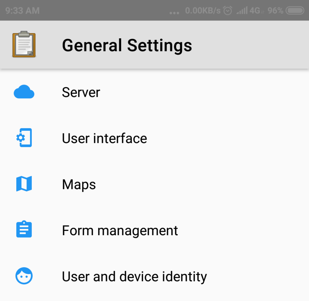
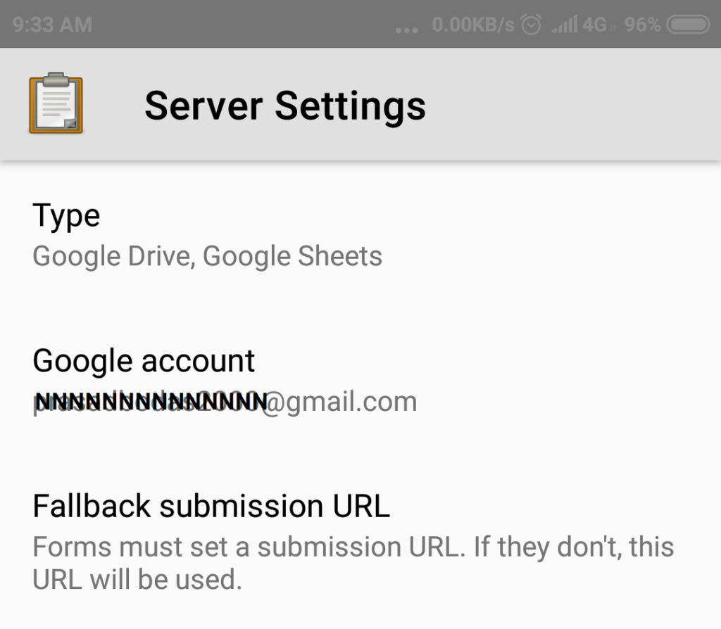
Select General Settings
Select option Server
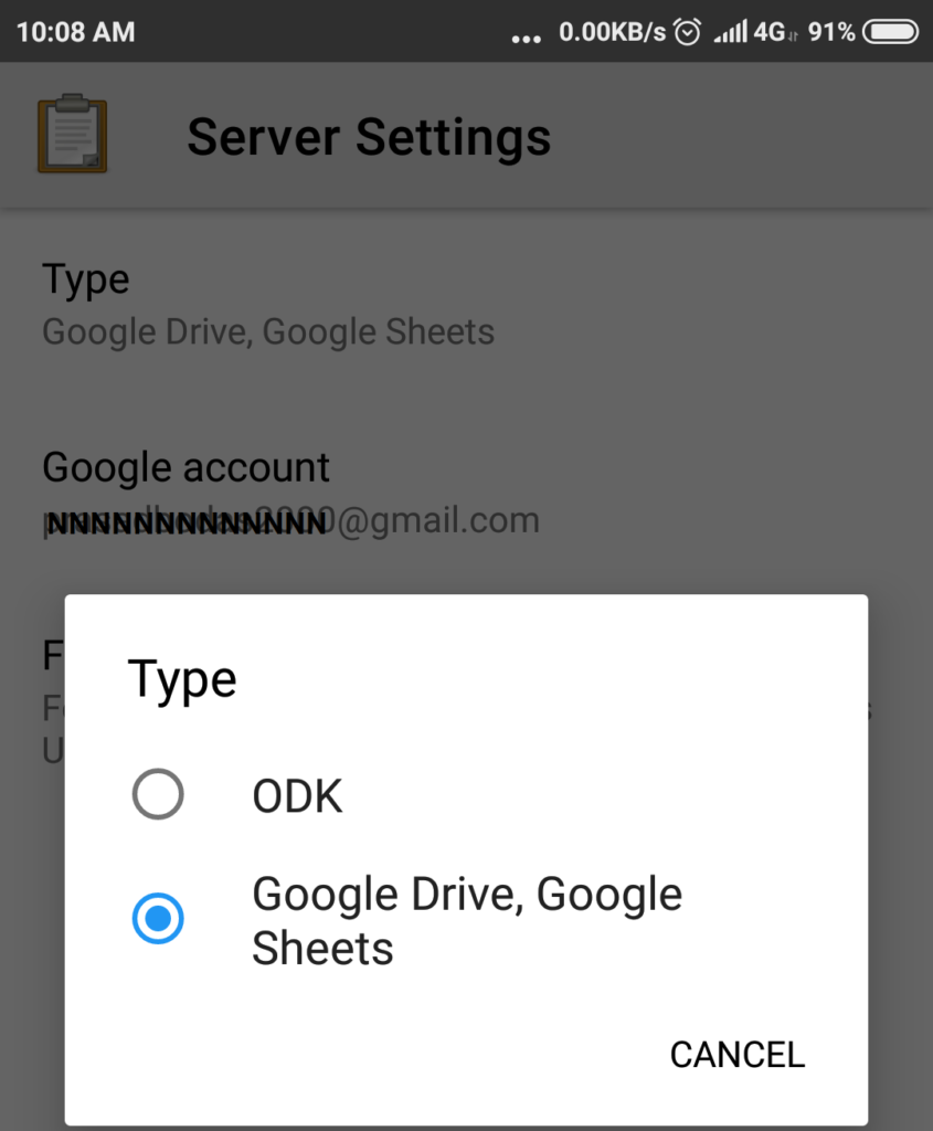
Select Type and Choose the value Google drive,Google sheets
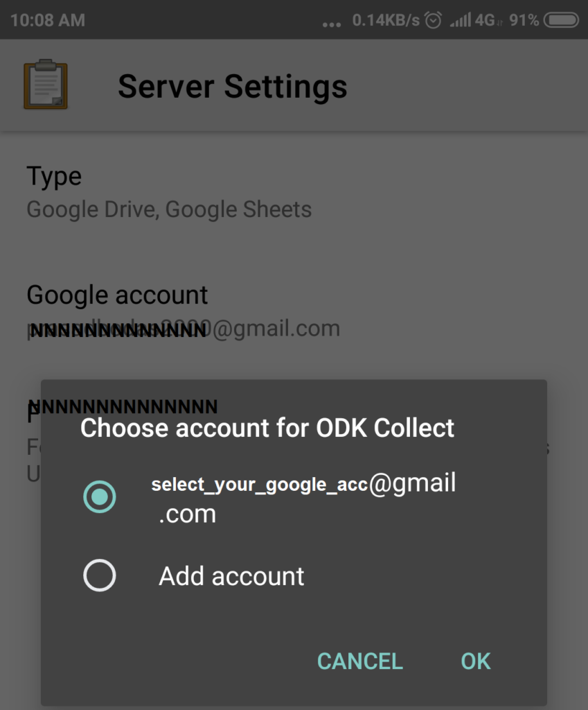
Select option Google account and when prompted choose or type your Google email id.
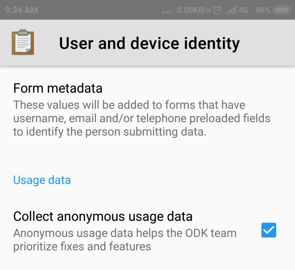
In General Settings select Option User and device Identity, a new page will show up as below.
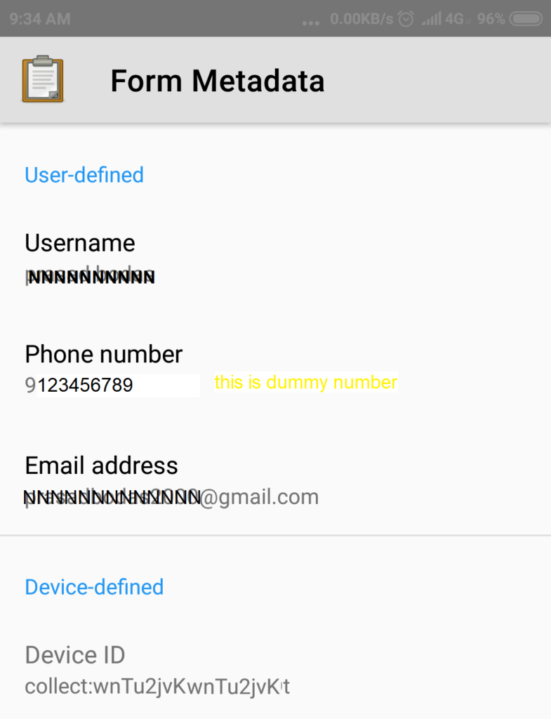
In this page select option Form metadata
A new screen will show up, in this screen select options User Name, Phone Number, Email Address one at a time and set correct values for each of these three parameters.
For user name make sure that your name (say first name and last name seperated by space or underscore character) will not duplicate with any other person’s name working on the same survey.
Include underscore or suffix (say 2001) or simply enter your Gmail id in the User Name field, so as to always make sure of it to be unique.
The fourth parameter is Device ID, let the value whatever it is set on this parameter as a defualt, be left as it is.
Fetching Form Master Data (End User)
Fetching Form Master Data requires data connectivity enabled on your mobile phone.
After the ODK Collect app is configured as given in previous step, then on the main page of the app click button Get Blank Form.
It will show a popup message with some text saying Reading Files.
After some time it will show contents of the Google drive for you as the Google drive user. If you are a form designer yourself and if you have created any forms, then the same will be shown here in the list.
In the lower side buttons click Shared with Me, this is required so as to get access to forms that other form designers / admin users may have shared with you.
Once clicked it will show Reading Files message.
Then it will show the list of files available /accessible to you as may have been shared with you.
It will show Files and Folders shared with you by other Google Drive users. A form file is most often a .xml file, as seen in few samples in the above image. Please contact your team lead / admin user in your group who can give you the exact names of the working forms for getting access to those forms.
Once the form name/form file name is know to you, select the form file on which you have been asked to capture the data, and then click Download Selected button at lower part of screen. It will show some saying – Fetching files, let it complete the processing.
After successful fetching of the form, it will show success message as below.
Capture Data At Actual Site Location (End User)
Data capture work can be performed entirely in offline mode and network connection and mobile data on the phone is not necessary.
If the survey includes any questions or data elements to capture Geo Location point (lat long) then GPS on the phone MUST BE enabled with high accuracy.
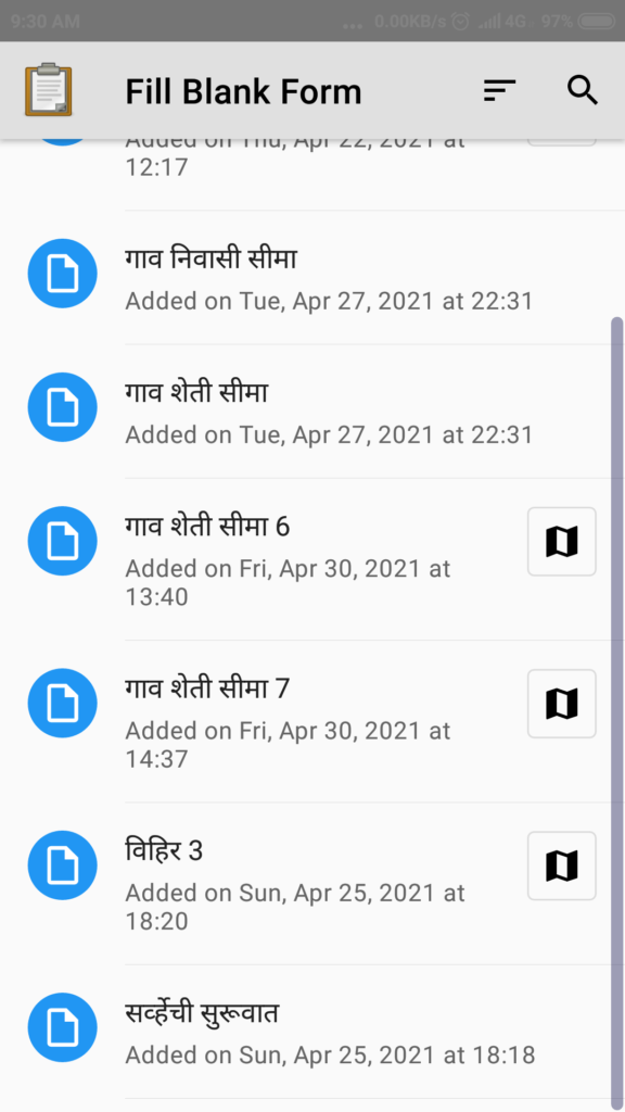
On main page of the ODK Collect app, click Fill blank form button. On the following page the forms fetched/downloaded so far will be displayed.
Select a form that you want to use for data capture, then the app will go on asking questions from that form sequentially, and it will allow navigation through the questions.
Questions and their response entry fields are different based on each question type as may have been configured by the Admin User.
Please go on responding with appropriate answers till the end.
Answer/response to some of the questions may be mandatory so user can not go to next question untill values are captured.
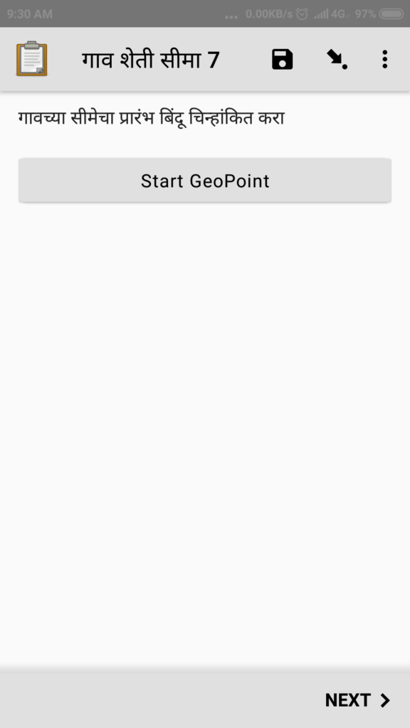
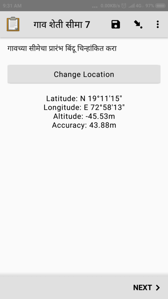
A single Geo location point where latitude and longitude needs to be capture will appear something like below.
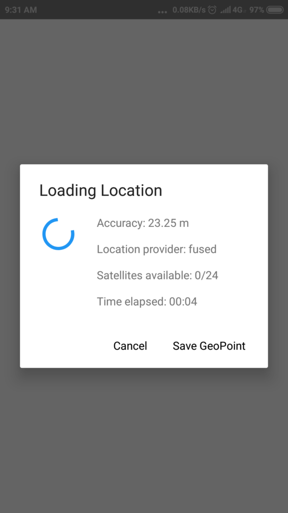
With GPS enabled on your phone, wait for some time till the accuracy improves to 2 or 4 meters or better and then click Save GeoPoint button. Image shown below only a sample, and was captured indoors when no GPS satellite was accessible to the phone, hence it shows very poor accuracy of more than 20 meters.
Once saved the GeoPoint will appear like below, after ensuring the accuracy value, proceed to Next or capture the point again by clicking the button Change Location.
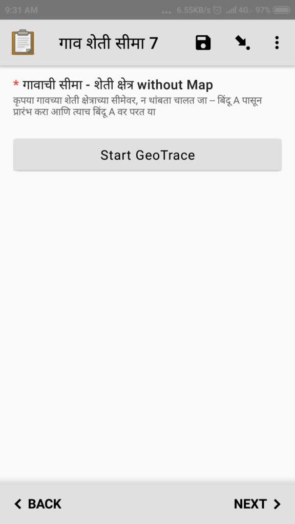
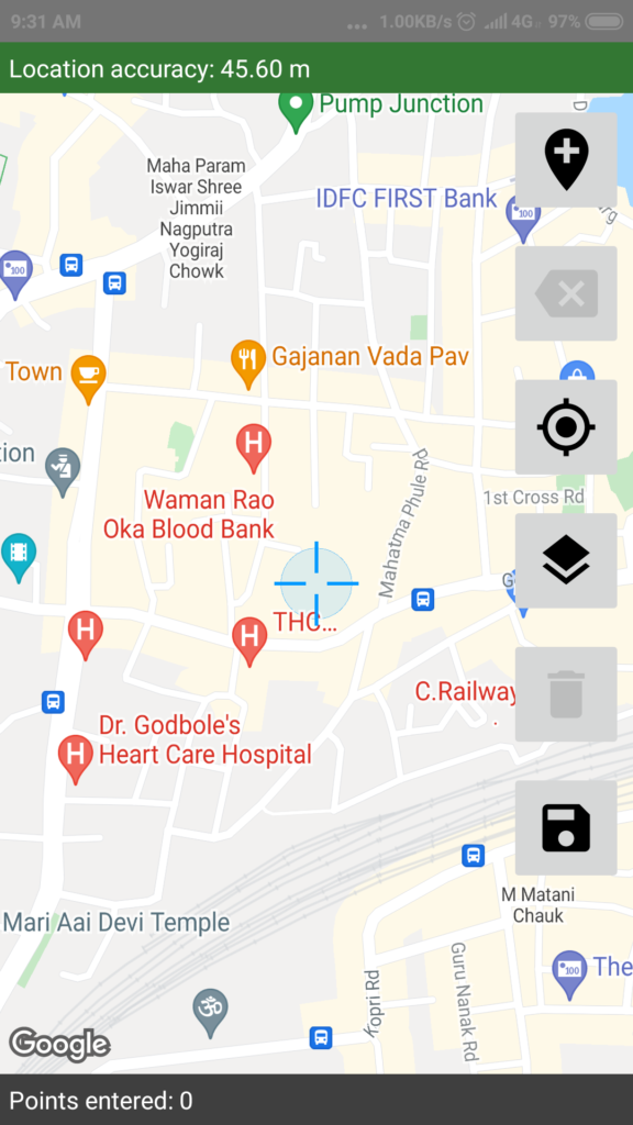
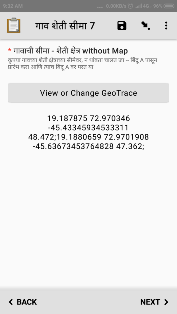
Next sample question is for capturing a GeoTrace (multiple Geo points).
Most likely if mobile network and data connection is not available then the map may not show at all or will show with very coarse resolution, refer next image.
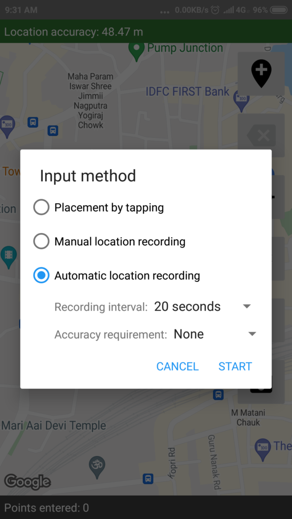
It is important to use the correct method for capturing the points in a Geo Trace. By clicking the first icon with + sign, at the right side edge of the page, select the Automatic location recording option, specify values for Recording Interval and Accuracy Requirement as shown and then click Start.
This is to be used while the end user walks around the object / entity being surveyed. For example if the user is capturing the GeoTrace near an open-well or a river, then the user needs to walk around the boundary with the auto option enabled. You can see that the ODK Collect app will record points continously every 10 or 20 seconds.
Once the boundary of interest is traversed as adequate then click the lowermost option for save which shows a disk icon.
After save click the values captured are displayed in a page like below.
Go throgh all the questions in the survey and capture the data to the fullest possible detail and accuracy. Please follow the instructions that may have been included by the Admin User for each question.
There can be various question types included in the survey as below.
Text
Number
DateTime
Date
Image
Audio
Video
Lat long – GeoPoint
Lat long list – GeoTrace
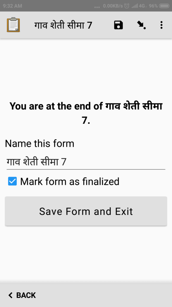
At the end of the survey questions the ODK Collect app will show a button Save Form and Exit, click that button to save the data captured.
Until so far the data captured is on the user’s phone and yet to be sent to the central common data repository/storage.
Send Form, Submit Data (End User)
Once you are done with the data capture as above you can / should submit the data.
For this you need mobile/data connection on your phone.
This activity can be performed from any location other than the survey site where mobile network or wifi connection is available and enabled on your phone.
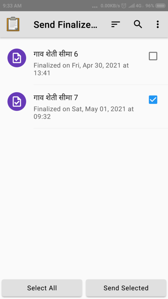
Once your phone gets the data connection, then on main page of the ODK Collect app, click Send finalised form button..
It will show a page where all the form which can be submitted will be displayed. Select one or more forms which are ready to submit and click Send Selected button.
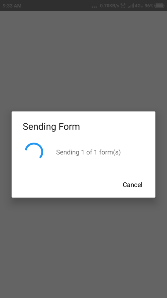
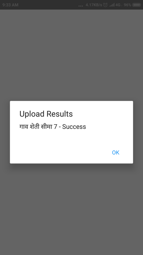
It will show Sending Form message, and finally it will show success.
Form submission success.
If any error occurs, please take a screenshot on your phone and send it to the admin user or entire team, so that suggestion about what to do on such error can be given.
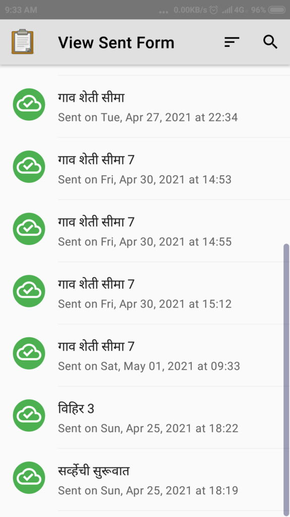
User can view all the submitted/sent forms. By clicking the button View Sent Form on the home page of the ODK Collect app.
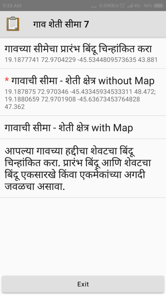
Any of the sent forms can be selected/touched/clicked and in the next page the app will show list of all questions in that form with captured data / answers shown briefly.
Pre-requisites for Survey Admin user
Admin user is a person who will prepare the survey questions and release the survey to the end users for data capture.
For each form to be used for data capture, below are the pre-requisites for admin user, these are in addition to all the prerequisites as applicable to the End User.
Create a blank Google spreadsheet in Google drive.
In Google Drive share the spreadsheet to all the data capture users, by adding their Google email Id.
Note down / copy the sharable URL of the spreadsheet file.
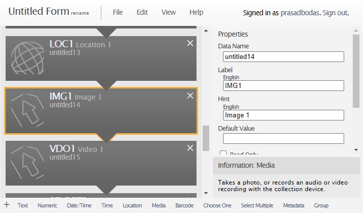
Create a Form layout using online form builder utility at this web site https://build.getodk.org/ This will require a login user id for yourself to be created first time.
Add the desired type and sequence of various questions.
Include the meta data system fields like user and phone number.
Specify the spreadsheet URL in the form properties – submission URL of the newly created form. Each form must have a different and distinct spreadsheet associated with it.
Export the form to local filesystem as XML format
Upload the form XML file in the Google drive.
In Google drive Share the form XML file to all the data capture users, by adding their Google email Id.
Avoid modifying the form design once the form is released for data capture and some data is already captured by the End Users.
If an existing form must be modified, deleting or renaming any existing question / field shall be avoided. Label and captions can be altered.
If a new question / field is to be added then corresponding field name must be added to the data capture Google spreadsheet as a new column after all existing columns and name of the new question / field needs to be manually entered as column label.
It is an interactive user interface for creating a data capture/survey form with various types of input fields or survey questions that can be added to the form. The instructions for form creation are not given here in details, and admin users are encouraged to explore the form builder web page, use the online documentation / help and get started with real forms that they want to create.
It is seen that it is best for the Admin users understand the form builder by doing hands on work.
Overall – How it Works / Conceptual Details
So far the activities to be carried out by End User and Admin User were exaplained.
For a given form, it may be so that one or more users are asked to capture data using the same form but for various different survey objects (locations or sites), as below.
User 1 – Location 1, Location 2
User 2 – Location 3, location 4 and location 5
User 3 – Location 1, location 3 and location 6
The data captured by multiple users as above will result in 8 instances of the same form captured on 3 different mobile phones of the 3 different end users. Notice that for Location 1 and Location 3 two different users were asked to capture the data, this may be intentional or otherwise.
All this data gets saved into respective mobile phones and when forms are sent by the users, it gets saved on the Google drive of the form creator user in a structured manner. There will be 2 each responses /datasets captured for Location 1 and Location 3, whereas other locations will have only one dataset.
The data captured from all users after they sent their respective forms needs to be programmatically fetched and interpreted, organized, processed and saved into some databse where it can be displayed or represented in a manner required by the project team.
With a question of type GeoTrace below processing can be useful to better understand the data captured.
To display the set of points as a track on Google map for all the points.
To calculate the perimeter distance and area of the boundary identified by the points.
To group various survey objects (say water-bodies) by their range/span of GeoTrace values.
All of the above.
We are in process of implementing a utility which can do such type of data processing using the data collected in ODK forms.
This will be deployed in our web site https://www.pbodas.in/ and will be made available to the logged in users. The users will need to permit the portal to access their respective Google drive files.
ODK Collect also works with a backend server instead of Google sheets, but that most often is a paid option which requires some server hosting and associated infrastructure management. Using Google sheets as the data capture mechanism is easier and free of cost as of now. Hence the same is highly recommended for community work and projects.
Please use ODK Collect app as explained above and provide your comments / feedback on this article.